
MOLD ENGINEERING / TOOLING FUNDAMENTALS
Optical Lens Mold vs. Standard Plastic Mold: What Actually Makes Them Different
Not all injection molds belong to the same engineering discipline. While an optical lens mold and a standard plastic injection mold share the same fundamental hydraulic or electric press, their engineering design, machining requirements, and production acceptance criteria can differ substantially.
By: ATRMOLD Engineering Team
October 2026
Reading time: 10min
Category: Mold Engineering
STANDARD PLASTIC MOLD
VS
OPTICAL LENS MOLD
The Short Answer:
An optical lens mold and a standard plastic mold differ across four core engineering areas. In optical lens mold manufacturing, these include surface finish (optical-grade polishing vs. standard SPI finishes), core and cavity machining (sub-micron Single-Point Diamond Turning vs. conventional 5-axis CNC/EDM), thermal and shrinkage control (cooling strategies designed to manage residual stress and shrinkage vs. standard thermal management), and qualification criteria (optical performance validation vs. dimensional inspection alone).
1. Technical Comparison: Optical Lens Molds vs. Standard Plastic Molds
2. 6 Key Differences Between Optical Lens Molds and Standard Plastic Molds
Search queries such as optical injection mold, precision lens mold, and optical-grade tooling often reflect a critical sourcing question: Is your tooling partner employing dedicated optical engineering protocols, or are they simply adapting standard plastic tooling practices to a component that demands sub-micron physics?
The six comparison points below explain why standard plastic tooling practices may not meet the requirements of optical applications.
2.1 Surface Topology & Micro-Finish (Ra vs. P-V)
One of the most visible differences is the required surface form and finish.
STANDARD PLASTIC MOLD
Finished to SPI B or C grades. Micro-machining marks or light textures are acceptable, when surface appearance and texture do not affect the part’s intended function.
OPTICAL LENS MOLD
May require an SPI A-1 finish, with arithmetic average roughness of Ra ≤ 5 nanometers and peak-to-valley (P-V) form error < 0.2 µm, depending on the optical design.
Why It Matters:
In optical injection molding, the mold surface is replicated on the molded polymer part. Any microscopic tool chatter, EDM pitting, or directional polishing scratches can increase light scattering, haze, and stray light in the final optical system.
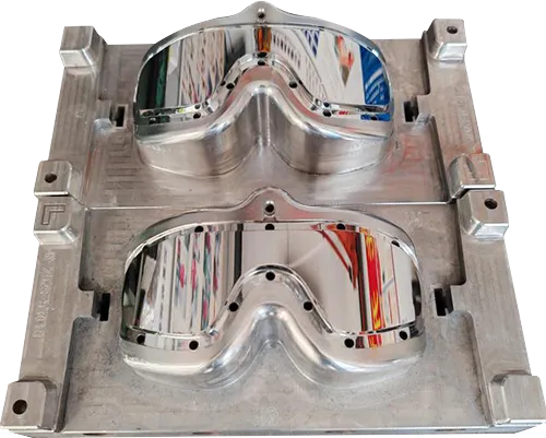
Precision injection mold with polished optical lens cavities for protective eyewear.
2.2 Core & Cavity Machining: Sub-Micron SPDT vs. Conventional CNC
How optical surfaces are machined in the mold inserts affects the form accuracy and surface finish achievable in the molded lens.
Conventional milling and EDM cut basic geometry, followed by manual hand polishing that risks altering optical form accuracy.
Depending on the material and optical requirements, precision machining and polishing can produce the required surface finish while maintaining optical form accuracy.
STANDARD PLASTIC MOLD
Machined via conventional high-speed CNC milling and Electrical Discharge Machining (EDM). These processes can produce accurate basic geometries, but surface marks and EDM-affected layers may require additional finishing before the inserts meet optical specifications.
OPTICAL LENS MOLD
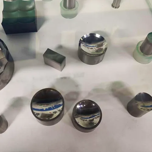
Optical inserts may be machined using Single-Point Diamond Turning (SPDT) or ultra-precision grinding, depending on the insert material and required geometry. SPDT can achieve sub-micron profile accuracy on suitable materials, including electroless nickel-plated surfaces and selected copper alloys.
Why It Matters:
Machining methods and optical mold steel selection (e.g., S136 vs. NAK80) must be co-engineered. Material inclusions or carbide clusters can damage diamond tools during SPDT and contribute to surface defects, depending on the steel grade and machining conditions.
2.3 Wall Thickness Inversion & Differential Shrinkage Behavior
A common principle of plastics design for manufacturability (DFM)—maintaining reasonably uniform wall thickness—must be considered alongside the optical geometry in lens design.
STANDARD PLASTIC MOLD
DFM guidelines generally favor uniform wall thickness to promote more consistent cooling and reduce the risk of sink marks, voids, and differential shrinkage.
OPTICAL LENS MOLD
A lens’s optical power and geometry determine its cross-sectional thickness (e.g., thick center for biconvex lenses, thin center for concave lenses).
Why It Matters:
Variable wall thickness causes differential volumetric thermal contraction. As the gate freezes off during the packing phase, thicker sections cool slower and experience localized sink. In precision optics, a localized sink of just 1 to 2 microns may affect surface form, shift focal length, or increase aberration, depending on the lens design and acceptance tolerances.
Q: Can a standard mold shop simply “upgrade” a tool to optical grade by adding extra hand polishing?
Not by itself. Hand polishing can alter the optical surface profile if it is not tightly controlled, so it cannot reliably compensate for an insert that lacks the required form accuracy. Optical-grade performance depends on suitable insert machining and finishing, controlled material quality, appropriate molding conditions, and management of thermal and residual stress. Polishing an out-of-spec curve only produces a shiny, optically distorted lens.
Q: Does optical tooling always require higher capital investment than standard tooling?
Generally yes, for the reasons covered in this guide — precision machining, tighter steel tolerance, and optical validation testing all add cost. Our optical lens injection molding cost guide breaks down exactly where that premium comes from.
2.4 Optical Lens Mold Gate Design and Flow-Induced Birefringence
The point where the polymer melt enters the cavity influences flow, residual stress, and optical performance.
STANDARD PLASTIC MOLD
Gate location is dictated by cavity filling balance, cosmetic concealment, and easy manual/automatic degating. Visible gate vestiges rarely impact functionality.
OPTICAL LENS MOLD
Gate geometry (fan, film, or contoured edge gates) influences shear rate, molecular orientation, and thermal history near the optical clear aperture (CA).
Why It Matters:
This connects directly to DFM review for optical lens injection molding and to birefringence in molded optical lenses — gate design is one of the earliest decisions that determines whether birefringence becomes a production problem later.
2.5 Thermodynamic Response & Conformal Cooling Design
Thermal management in an optical mold affects not only cycle time but also molecular relaxation, shrinkage, and replication of the mold surface.
STANDARD PLASTIC MOLD
Straight-drilled cooling channels are typically sufficient. Temperature differences across the core and cavity may be acceptable when they do not compromise the part’s specified requirements.
OPTICAL LENS MOLD
Non-uniform mold wall temperature is a primary cause of localized refractive index variation, lens warpage, and optical astigmatism. Some optical molds use conformal cooling channels or high-thermal-conductivity beryllium-copper or AMPCO inserts to improve temperature control near contoured surfaces.
Why It Matters:
Temperature variations across the cavity, including those approaching ±0.5°C during packing and cooling, can affect shrinkage and residual stress, potentially shifting focal length beyond specified limits. As outlined in an optical lens tolerances guide, the impact depends on the material properties and lens design.
2.6 Multi-Cavity Optical Consistency & Acceptance Metrology
What “mold sign-off” actually means differs fundamentally between the two disciplines.
STANDARD PLASTIC MOLD
Qualification relies on dimensional inspection using Coordinate Measuring Machines (CMM) or optical comparators. Acceptance is granted when physical dimensions fall within the specified engineering tolerance band (e.g., ±0.05 mm).
OPTICAL LENS MOLD
Dimensional compliance is a prerequisite. Final sign-off requires optical validation as required by the specification, which may include spectral transmittance, wavefront testing (using a Shack-Hartmann sensor or Zygo interferometer), modulation transfer function (MTF) measurement, and birefringence analysis.
Why It Matters:
In a multi-cavity optical tool, Cavity 1 and Cavity 8 may show identical measurements on a CMM yet produce different focal lengths or wavefront distortions due to subtle flow imbalances (< 0.1% pressure variance) or residual stress, even when their measured dimensions are similar. As explained in our multi-cavity optical lens mold consistency guide, dimensional checks alone cannot guarantee consistent optical performance across cavities. A quality control and metrology guide should also address optical measurements to verify that each cavity produces components that meet the specified optical requirements.
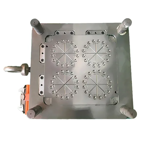
3. Optical Mold DFM: 4 Key Engineering Risk-Control Areas
To help move a precision lens program from CAD to mass production, use this four-pillar engineering evaluation framework before cutting steel.
Pillar 1 Thermal Stress & Birefringence Simulation
- Flow & Polarization Analysis: Run mold-filling simulations (e.g., Moldflow / Moldex3D) configured for the selected optical polymer (PMMA, PC, COP, OKP) where suitable material models are available. Use the results to assess flow behavior and potential stress-related risks before steel machining.
- Gate Geometry Optimization: Evaluate fan or extended film gates outside the clear aperture (CA), where the part design permits, to reduce high shear near the optical path and limit stress concentration.
Pillar 2 Material Metallurgy & SPDT Machining Readiness
- Electroslag Remelting (ESR) Verification: Specify suitable ESR steels (e.g., Uddeholm Stavax ESR / S136) for core and cavity inserts where required by the application; material cleanliness can help reduce the risk of surface defects during machining and finishing.
- Surface Finish and Form Specifications: Define surface roughness and form requirements on technical drawings using Ra ≤ 5 nm and peak-to-valley form error P-V < 0.2 µm, rather than relying on generic polishing notes.
Pillar 3 Cavity Thermal Equilibrium & Shrinkage Compensation
- Conformal Thermal Management: Evaluate conformal cooling passages or high-thermal-conductivity inserts where appropriate to control mold-surface temperature variation; any target, including ≤ ±0.5°C across the optical surface, should be validated for the specific mold and process.
- Non-Uniform Shrinkage Compensation: Apply validated shrinkage compensation to the mold design and, where appropriate, the SPDT tool path to account for variable cross-sectional thickness and reduce the risk of localized sink or form deviation.
Pillar 4 Dual-Stage Metrology Protocol (Dimensional + Optical)
- Unified Metrology Alignment: Establish sign-off criteria that combine dimensional and surface measurements (CMM / stylus profilometry, as appropriate) with optical performance testing (Shack-Hartmann wavefront sensing, modulation transfer function (MTF), and transmittance).
- Multi-Cavity Optical Cpk Tracking: Where suitable measurement methods and sufficient production data are available, assess multi-cavity process capability using optical metrics such as focal length variation and wavefront error, rather than relying on external dimensions alone. Apply Cpk ≥ 1.33 only where this acceptance criterion has been agreed.
Conclusion: Sourcing Two Distinct Engineering Disciplines
An optical lens mold and a standard plastic mold are not different quality tiers of the same skill—they are fundamentally distinct engineering disciplines executing on similar machinery. Surface topology, sub-micron machining, gate shear management, conformal thermal control, and optical metrology diverge in ways that compound rapidly.
A tooling supplier experienced in standard structural housings will not automatically have the ultra-precision equipment and processes required for optical-grade components. Evaluating these engineering requirements early can reduce the risk of costly redesigns and help ensure that the molded optics meet performance requirements during optical testing.
Ready to Engineer Your Precision Optical Tooling Program?
Consult the ATRMOLD engineering team to review your lens design, optical mold steel selection, DFM considerations, and multi-cavity consistency requirements.
Related Reading — The Mold Engineering Cluster
One comment
Comments are closed.
[…] choice between a hot runner and a cold runner system for an optical lens mold isn’t primarily a cost decision; it’s an optical one. Gate type and runner design […]