
Six Optical Manufacturing Services — Design Through Mass Production
ATRMOLD provides integrated optical manufacturing services covering every stage of product development — from initial lens design and DFM analysis through precision mold fabrication, cleanroom injection molding, and secondary molding processes. Single-vendor control across all stages eliminates inter-supplier variation and simplifies quality accountability.
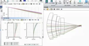
Optical Design & Simulation
Ray tracing alone misses shrinkage and stress critical to injection-molded optics. Our engineering team integrates optical simulation with mold-flow analysis before tooling begins — identifying gate-induced birefringence, sink mark risk, and tolerance stack-up failures at the design stage, where corrections cost days rather than weeks.
- Imaging and illumination lens design for custom optical systems
- Integrated ray tracing and mold-flow simulation for production accuracy
- Tolerance stack-up analysis and DFM review before tooling commitment
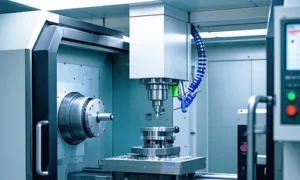
Precision Mold Manufacturing
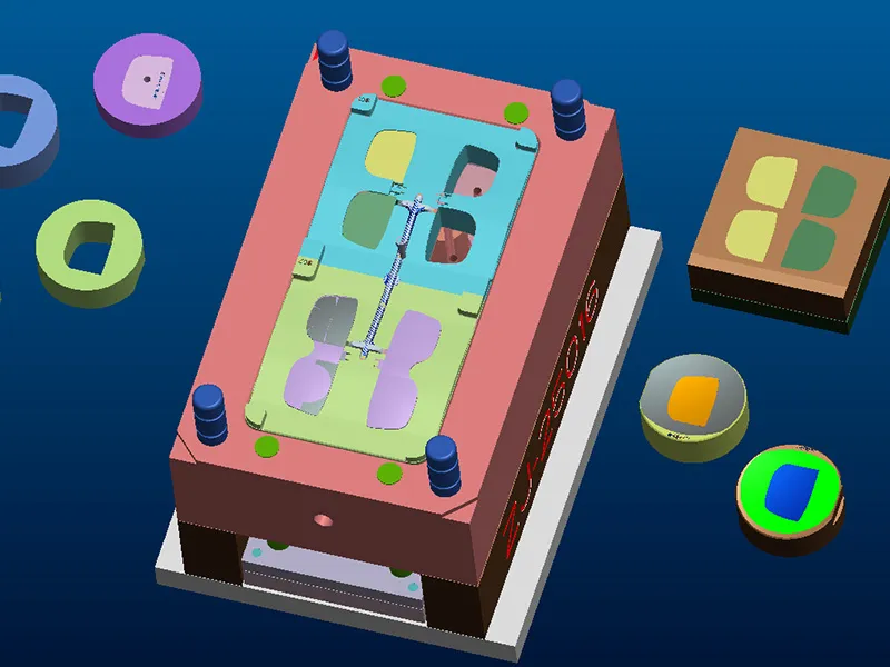
As a precision lens mold maker with 20+ years of optical tooling experience, ATRMOLD manufactures aspheric lens molds, Fresnel lens tooling, and multi-cavity optical molds on 5-axis CNC and single-point diamond turning (SPDT) equipment — achieving surface finish to SPI A1 standard (Ra ≤10 nm).
- Optical structure evaluation and DFM analysis before tooling commitment
- Single-point diamond turning (SPDT) to Ra ≤1 nm cavity surface accuracy
- Diamond polishing to SPI A1 standard — eliminates mid-spatial-frequency scatter
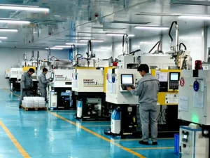
Optical Lens Injection Molding
All optical lens production runs in ISO Class 7 (Class 10,000) cleanrooms, with a dedicated ISO Class 6 (Class 1,000) zone for highest-specification components. FANUC all-electric machines provide closed-loop process control. SPC monitoring runs throughout each production batch.
- Multi-cavity molds with cavity-to-cavity balance analysis
- Advanced conformal cooling for repeatable cycle-to-cycle dimensional stability
- In-process SPC monitoring — Cpk targets defined per customer specification
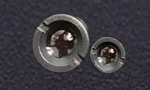
Overmolding
Two-shot and insert overmolding for optical assemblies requiring integrated soft-touch grips, sealing elements, or secondary optical surfaces. We manage substrate compatibility, bond strength, and dimensional integrity across both materials and both shots.
- Two-shot overmolding for integrated optical and structural components
- Substrate compatibility analysis — adhesion, shrinkage differential, warpage
- Suitable for sealed sensor housings, ergonomic grip optics, and hybrid assemblies
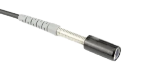
High-Temperature Injection Molding
Processing of engineering-grade resins including LCP, PEEK, PPS, and high-temperature PC for optical components operating above 150°C. Mold temperature control and barrel configuration are matched to each material’s processing window to avoid degradation and maintain optical clarity.
- Materials: LCP, PEEK, PPS, high-temp PC — continuous use to 260°C
- Mold temperature control via pressurized water and oil systems
- Suitable for automotive under-hood sensors, LED driver optics, and industrial imaging
Insert Molding
Metal inserts, threaded brass inserts, and functional substrates are molded directly into optical components in a single production step — eliminating secondary assembly operations and improving dimensional repeatability of insert-to-optical-surface relationships.
- Metal and threaded insert molding in a single production step
- Eliminates secondary assembly — reduces part count and tolerance stack-up
- Suitable for sensor housings, mounting flanges, and fiber optic connectors
Why Optical-Grade Injection Molding Requires a Different Approach
Standard injection molding tolerates dimensional variation that an optical lens cannot. Three engineering factors distinguish optical-grade molding from general-purpose plastic production — and each must be controlled simultaneously, not independently.
Birefringence Control
Injection molding introduces two sources of internal stress: flow-induced stress from molecular orientation during cavity filling, and thermal stress from uneven cooling. Both cause birefringence — a spatially varying change in refractive index that distorts wavefront and degrades image or signal quality. For sensor lenses, AR/VR optics, and medical imaging components, birefringence is a functional defect, not a cosmetic one. Gate position, fill speed, and mold temperature must be optimized together to minimize it.
Shrinkage Compensation
PMMA shrinks approximately 0.2–0.8% during cooling; PC behaves differently, and COC/COP differently again. Mold cavities are scaled to compensate — but compensation values must be validated against production data from the specific material lot and mold configuration, not taken from a datasheet. Unvalidated shrinkage assumptions are the most common cause of first-article dimensional failures on optical lenses.
Surface Finish at Optical Scale
General mechanical parts are considered smooth at Ra 1–3 µm. Optical-grade surfaces require Ra closer to 10 nm — roughly 100–300× finer — because surface irregularities at the nanometer scale scatter light, reduce MTF, and degrade signal clarity. Achieving and verifying this finish requires diamond-turned mold inserts, controlled polishing procedures, and surface profilometer measurement on every tool before production release.
OEM/ODM Optical Lens Development: From Requirement to Mass Production
Most optical OEM/ODM projects arrive either as an application requirement without a design, or as a finished design that has never been validated against real injection molding behavior. Our four-stage process is built to handle both — and to eliminate the tooling rework cycles that make optical product development expensive.
Development Process:
- Requirement Analysis: We translate your application scenario — detection distance, wavelength, operating temperature, mechanical envelope — into concrete optical and material targets before any design work begins.
- Optical Design & DFM Review: Optical design and DFM review proceed in parallel. The lens geometry that looks correct in ray-tracing simulation is simultaneously evaluated for moldability — wall thickness uniformity, gate position relative to optical surfaces, and cooling layout for the selected material.
- Prototyping & First-Article Validation: Prototype samples are measured against your original optical specification — focal accuracy, transmittance, wavefront error, and dimensional fit — before any commitment to mass production tooling. FAI reports and inspection data are provided at this stage.
- Scalable Mass Production: Process parameters validated during prototyping are locked, documented, and monitored through full-volume production ramp-up via SPC. The part that passed validation is the part you receive at 500,000 units.
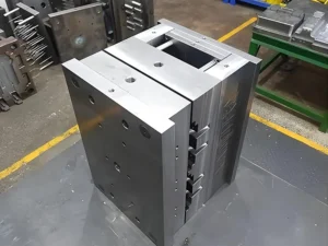
Precision optical mold design and manufacturing
Molds are the core of optical products. With 20+ years of experience and diamond ultra-precision equipment, we hold dimensional tolerances down to ±0.025mm on critical optical features — within the precision band defined by ISO 20457 and DIN 16742 for optical-grade injection molded parts.
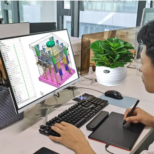
Optical Structure Evaluation
Comprehensive optical design review, structural feasibility assessment, and DFM analysis are performed before tooling commitment — ensuring geometry, tolerances, and material selection are validated against real production constraints, not only CAD assumptions.
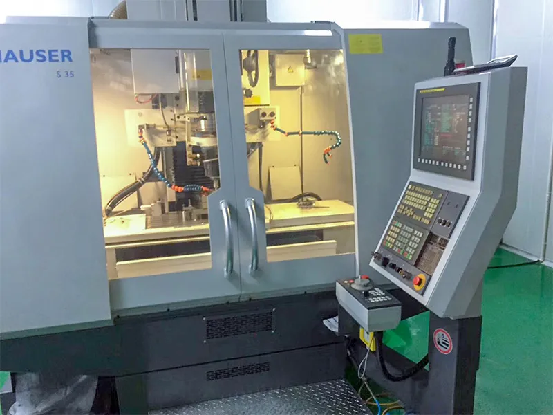
Ultra-Precision Machining
Single-point diamond turning (SPDT) achieves cavity surface accuracy of Ra ≤ 1 nm, meeting the surface finish requirements of aspheric and freeform optical cores — where sub-nanometer errors directly degrade MTF and introduce measurable wavefront aberrations.
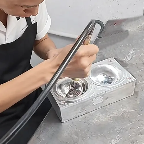
Diamond Turning & Polishing
Optical-grade core polishing to SPI A1 standard eliminates mid-spatial-frequency errors that scatter light and reduce MTF, ensuring consistent transmission and surface quality across high-volume production runs.
Dimensional Inspection & Engineering Verification
Precision measurement and engineering verification confirm every mold component meets design specifications and manufacturing tolerances before mold trial — eliminating avoidable first-article failures.
- Documented inspection procedures with traceability records
- In-process audits at critical production stages
- First article inspection (FAI) per customer drawing
- CMM dimensional verification to ±0.005 mm
- Surface profilometer measurement of Ra and Rz values
- Material certificate and traceability records per batch
Optical Lens Quality Control: ISO 9001 Inspection From Material to Shipment
ISO 9001:2015 certified quality management system ensures full-process quality control from raw materials to finished products. Each inspection stage targets a specific failure mode that is invisible to the naked eye but critical to optical performance.
| Stage | Process | Method | Target |
|---|---|---|---|
| IQC | Incoming material | Spectrophotometer + moisture meter | Refractive index, moisture <0.02% |
| IPQC | First-article inspection | CMM + surface profilometer | Cavity ±0.005 mm, Ra ≤10 nm |
| IPQC | In-process monitoring | SPC on all machines | Cpk per customer spec |
| OQC | Optical inspection | 100% visual + sampling MTF | Cosmetic quality per ISO 10110 (Scratch-Dig), focal accuracy per drawing |
| OQC | Dimensional final check | CMM per AQL 1.0 | All critical dims within tolerance |
| Shipment | Documentation | CoC + FAI + SPC data | Traceable to raw material lot |
Optical Lens Design Review: Why Early Engineering Involvement Reduces Project Risk
We are not only manufacturers but also optical solution partners. Our engineering team reviews optical lens design before tooling begins — at the stage where changes are inexpensive and design flaws are still easy to correct.
Reduce Development Risk
Most optical lens design failures originate from assumptions that don’t survive contact with real injection molding: wall thickness that causes sink marks, gate placement that introduces birefringence, or tolerance stacks that exceed what the mold can hold. Reviewing these factors against material shrinkage data and mold-flow simulation before cutting steel typically eliminates two to three rounds of costly tooling rework.
Improve Optical Performance by 20%+
Optical performance gains come from aligning lens geometry with what the selected material and mold structure can reliably deliver — for example, repositioning gates to reduce flow-induced stress, or adjusting wall thickness ratios to control shrinkage-driven form deviation. These adjustments typically improve measured transmittance, focal accuracy, or distortion control by 20% or more compared to an unreviewed first design.
Shorten Development Cycles by 30%
Each mold trial-and-correction cycle for optical-grade tools typically takes 2–4 weeks. Catching dimensional or optical risk during the design stage — rather than after first-article inspection — removes at least one full correction cycle from most projects, cutting total development time by roughly 30%.
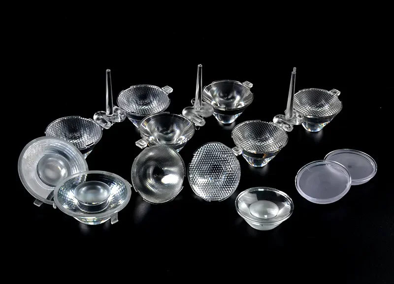
Custom Optical Lens Manufacturer for Automotive, Sensor & Medical Applications
Each industry imposes different optical and mechanical demands — automotive lenses must survive thermal cycling, medical lenses require biocompatible low-birefringence materials, and sensor lenses depend on consistent focal accuracy across millions of units. Our material selection and mold design adapt to these requirements case by case.
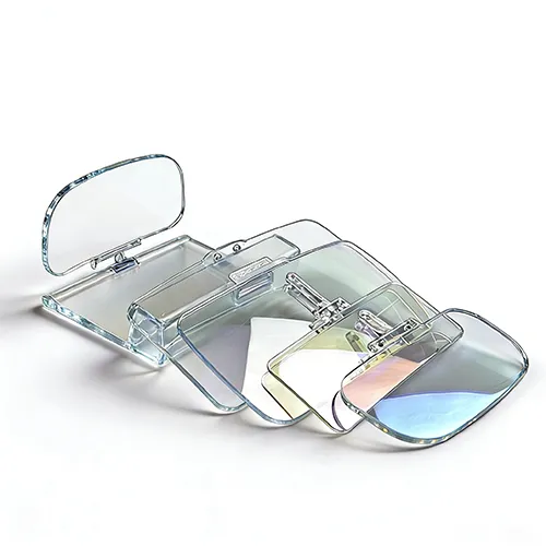
HUD reflectors and sensor lenses in PC for impact resistance and -40°C to 120°C thermal stability under the hood.
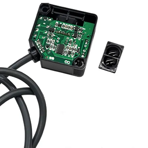
Photoelectric and proximity sensor lenses requiring tight focal length tolerances for repeatable high-volume detection.
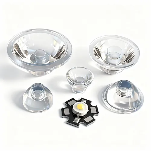
TIR and aspheric lenses engineered for beam angle control and uniform light distribution from a single LED source.
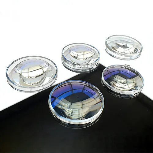
Aspheric imaging lenses with anti-reflective coating to minimize stray light and maximize transmittance for camera and machine vision systems.
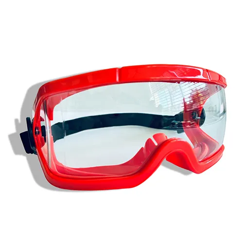
Impact-resistant PC lenses for protective eyewear, balancing optical clarity with mechanical durability under daily wear conditions.
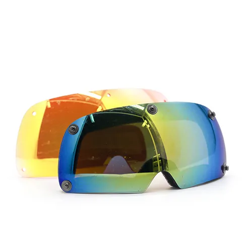
REVO mirror-coated and anti-fog lenses designed for glare reduction and long-term clarity retention in outdoor, high-humidity, and high-UV environments.
Optical Lens Manufacturing Process: From Requirement to Mass Production
A clear, engineering-led collaboration path from initial contact to delivery, giving you complete visibility into project progress and the technical decisions behind each stage.
Requirement Discussion
We review application requirements, optical performance targets (focal length, transmittance, distortion limits), dimensional tolerances, and end-use conditions such as temperature range and chemical exposure.
Engineering Evaluation
Optical design review, tolerance stack-up analysis, and mold-flow simulation identify shrinkage, warpage, and birefringence risk before tooling — reducing development risk at the stage where changes are still inexpensive.
Mold Development
Precision mold manufacturing using diamond turning and single-point diamond machining, with optical surface polishing and in-process dimensional inspection at each build stage.
Sampling & Validation
Trial molding produces first-article samples, which undergo optical testing (transmittance, focal accuracy) and dimensional testing (CMM measurement) before sample approval.
Mass Production
Stable injection molding with locked process parameters — barrel temperature, injection speed, and packing pressure are monitored continuously to ensure batch-to-batch consistency.
Delivery & Support
After final inspection and secure delivery, our engineering team remains available for design refinement, mold maintenance, and production support as your product evolves.
Optical Manufacturing Services: Frequently Asked Questions
Common questions from engineers and procurement managers deciding which optical design, mold, or molding service fits their project.
Yes, subject to engineering review of the existing mold and design. We assess tooling condition, optical performance against your specification, and whether the mold can be modified versus rebuilt, then provide a feasibility report and quote within 3–5 business days.
Yes. Most OEM/ODM projects start this way. Our optical design and engineering service begins with requirement analysis — translating your application scenario into concrete optical targets such as focal length, transmittance, and operating temperature — before any mold work begins.
Ray-tracing simulation models a perfect geometry; it does not model shrinkage, flow-induced stress, or birefringence introduced during actual injection molding. A design that performs correctly in simulation can still fail in production if these factors were not reviewed — this is the single most common reason optical projects need mold rework after tooling has already begun.
Both. We support full end-to-end projects from optical design through mass production, and we also take on single-stage work — for example, building a mold to your existing design, or producing parts from a mold you already own. Tell us your starting point and we’ll scope accordingly.
Sample orders of 50–100 parts are available for design validation. Production MOQ is typically 5,000–30,000 pieces depending on lens geometry and mold cavity count, with exact figures confirmed at the quotation stage based on your specific part.
Consistency starts at the mold stage with cavity-to-cavity balance analysis on multi-cavity tooling, then continues through production with locked process parameters — barrel temperature, injection speed, and packing pressure are monitored continuously rather than set once and left unchecked.
Engineering evaluation and DFM review typically take 1–2 weeks, mold development 5–7 weeks, and sample validation 1–2 weeks before mass production begins. Total timeline depends on lens complexity and whether the design has already been validated — projects starting from an unreviewed design generally take longer due to the design correction stage.
Start Your Custom Optical Lens Manufacturing Project Today
Looking for a reliable optical lens and mold manufacturing partner? Send us your drawings or requirements. Our engineering team provides DFM feedback within 24 hours.