
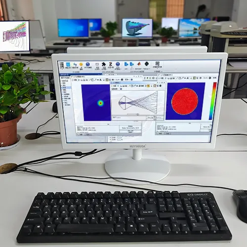
Standard injection molding DFM checks wall thickness and draft angles. Optical lens DFM must go further — into birefringence, gate-induced stress, mold-flow simulation, and tolerance stack-up against real cavity capability. The following outlines how this process is applied in production.
By: ATRMOLD Engineering Team
July 2026
Reading time: 14 min
Category: Optical Engineering
2–4 Wks
Cost of each mold rework cycle in lead time
1–2 Wks
Typical DFM review turnaround at ATRMOLD
~30%
Development timeline reduction with upfront DFM
1. Why Optical Lens DFM Is Different from Standard Injection Molding DFM
2. What Skipping DFM Actually Costs: A Realistic Breakdown
3. The 7 DFM Checks Specific to Optical Lens Projects
4. Deep Dive: Gate Placement and Birefringence Control
5. Tolerance Stack-Up: The Check Most Optical Designs Fail
6. Mold-Flow Simulation: What It Catches That Manual Review Misses
7. When to Run DFM: Timing Matters as Much as Content
8. DFM for Emerging Applications: LiDAR, AR Optics, and Humanoid Robot Vision
1. Why Optical Lens DFM Is Different from Standard Injection Molding DFM
Design for Manufacturability (DFM) for standard plastic injection molding is a well-understood process: check wall thickness uniformity, add draft angles, avoid sharp internal corners, and position the gate away from cosmetic surfaces. Follow these rules, and most commercial plastic parts can be tooled without major production obstacles.
Optical lenses break almost every standard DFM assumption.
The non-cosmetic surface where a standard DFM review suggests placing gates or ejector pins is often the optically active aperture of a lens. The uniform wall thickness recommended by standard DFM is frequently incompatible with meniscus, plano-convex, or doublet geometries where wall thickness varies by design. Furthermore, parting line placement — optimized by general molders solely for ease of ejection — directly dictates optical surface quality and symmetry.
Standard DFM fails to evaluate the variables that govern optical performance: birefringence from flow-induced molecular orientation, sub-micron surface replication fidelity, focal length shifts from differential shrinkage, and transmittance degradation from residual thermal stress. These are optical-specific failure modes requiring specialized engineering reviews.
ENGINEERING REALITY
We regularly receive lens designs from customers that have passed a standard DFM review, yet every optical-specific risk was missed. While the geometry may appear manufacturable to a general-purpose injection molder, an experienced optical lens manufacturer can quickly identify multiple risks likely to require extensive mold rework before the lens meets specification.
2. What Skipping DFM Actually Costs: A Realistic Breakdown
The argument against DFM usually centers on schedule constraints: “We are already behind schedule and cannot afford a two-week review before cutting steel.” This perspective overlooks the cumulative cost of mold rework in schedule, budget, and project execution.
| Project Stage | Action | Cost (Without DFM) | Cost (With DFM) |
|---|---|---|---|
| Pre-Tooling | DFM Review | $0 saved, problems undetected | $1,500–$3,000 review cost |
| Mold Trial 1 | First-article optical testing | Lens fails birefringence or dimensional spec | Lens meets spec or known deviation addressed |
| Mold Rework 1 | Gate relocation or cavity revision | $3,000–$15,000 + 2–4 weeks delay | Not required |
| Mold Trial 2 | Re-testing after rework | Often reveals second issue not visible in first trial | — |
| Mold Rework 2 | Wall section adjustment or venting change | $2,000–$8,000 + 2–3 weeks delay | Not required |
| Total typical impact | 3+ rework cycles on unreviewed optical molds | $10,000–$35,000 + 6–10 weeks delay | $1,500–$3,000 + 1–2 weeks up front |
The three-rework-cycle scenario outlined above is common in optical lens projects transferred from general injection molders. It reflects the data we gather from optical lens projects that arrive at ATRMOLD after failed tooling attempts at general molding shops. The first rework cycle usually addresses the most catastrophic failure (such as a missed dimensional or focal length specification). The second addresses secondary defects uncovered once primary dimensions are stabilized. By the third cycle, the project is 8–12 weeks behind schedule, and the customer has outspent the cost of an upfront DFM review by a factor of ten.
THE TIMELINE MATH
A two-week DFM review shifts the tooling start date by 14 days. A single mold rework cycle requires two to four weeks. Skipping DFM only saves time if the initial tooling produces conforming first articles without requiring mold modifications. In precision optical molding, zero-rework yields without upfront DFM are exceedingly rare.
3. The 7 DFM Checks Specific to Optical Lens Projects
A rigorous optical DFM review addresses specific failure modes that standard mechanical DFM underweights or omits entirely.
Gate Location and Birefringence Risk
The single most impactful DFM decision for optical performance. Residual stress concentrates at the gate area — verified by polarimetry studies showing maximum birefringence at or near gate locations. Gate position determines where this stress sits relative to the optical zone. A gate placed in or near the optical path disqualifies the lens from most precision optical specifications regardless of how well every other variable is controlled.
Impact: Critical — disqualifying if wrongWall Thickness Ratio and Shrinkage Uniformity
Optical lenses with varying wall sections — meniscus, aspheric, or compound geometries — shrink at different rates across the part. The DFM review maps expected shrinkage variation across the lens geometry and identifies sections where differential shrinkage will cause measurable surface form deviation. Mold cavity compensation is designed from this analysis, not from a single shrinkage figure on the material datasheet.
Impact: Critical — affects focal length and surface formTolerance Stack-Up Against Mold Capability
Optical specifications often assign tolerances to individual features without checking whether the combined stack-up of dimensional variation is achievable within what the mold and process can hold. This check compares the tolerance budget across all critical dimensions against real mold capability data — not theoretical material shrinkage figures.
Impact: Critical — determines whether the design can be produced in volumeParting Line Placement and Optical Surface Integrity
Parting line location on an optical lens determines where flash risk exists and what post-processing (if any) is required. For precision lenses, the parting line should never cross an optically active surface. Parting line placement also affects cooling channel routing and mold steel mass distribution, which influences thermal uniformity during production.
Impact: High — affects surface quality and production yieldDraft Angle and Optical Surface Ejection
Optical surfaces require SPI A1 mirror finish, which means contact between the molded surface and the cavity during ejection must be clean. Draft angles for optical lenses are smaller than standard DFM recommendations because high draft distorts lens geometry — but too little draft causes drag marks during ejection. This review finds the balance point specific to lens geometry and material.
Impact: High — affects surface quality and mold lifeRunner and Gate Type Selection
Cold runner vs. hot runner, pin gate vs. tunnel gate vs. film gate — each affects flow balance, shear stress at the gate, and weld line formation. For multi-cavity optical lens molds, runner balance is especially important: unbalanced fill causes cavity-to-cavity variation in shrinkage and birefringence, producing lenses from different cavities that perform differently despite identical tooling.
Impact: High — critical for multi-cavity mold consistencyCooling Channel Layout and Thermal Uniformity
Non-uniform cooling is a primary cause of warpage and birefringence in optical lenses. The DFM review evaluates cooling channel placement relative to lens geometry and checks that mold temperature uniformity can be maintained within the range required for the specified material and optical tolerance. Conformal cooling (channels that follow the lens surface contour) is sometimes required for tight-tolerance lenses that conventional straight-drilled channels cannot cool uniformly.
Impact: Medium-High — affects warpage and cycle time4. Deep Dive: Gate Placement and Birefringence Control
Gate placement dictates optical quality and is the most consistently misengineered variable when optical components are designed by teams lacking manufacturing experience.
Birefringence in injection-molded lenses stems from two sources: flow-induced stress (molecular chain orientation during cavity filling) and thermal stress (differential cooling rates across variable cross-sections). Both stresses concentrate heavily at the gate. Polarimetry analysis confirms that residual stresses peak at the gate entry point due to the abrupt geometric transition, which induces high shear stress as the polymer melt accelerates into the cavity.
Practical Implementation for Gate Placement
The gate should be positioned completely outside the clear aperture of the lens. Residual stress from the gate creates localized birefringence, which manifests as wavefront error in imaging systems, pattern distortion in structured light projectors, and polarization cross-talk in sensor systems like solid-state LiDAR.
❌ COMMON ERROR
Center Gate on a Circular Lens
This layout appears efficient because it offers the shortest flow path and symmetric cavity filling. However, it concentrates maximum residual stress directly at the optical center where light paths are most critical. The resulting lens frequently fails wavefront specifications despite passing all physical dimensional inspections.
✅ CORRECT APPROACH
Edge Gate Outside the Clear Aperture
The gate is positioned on an extended edge tab or flange outside the optically active zone. Residual stress concentrates within the gate vestige area, safely away from the light path. This significantly reduces birefringence within the clear aperture, while the gate vestige remains outside the optical path.
The Warpage vs. Birefringence Engineering Tradeoff
There is a fundamental engineering tension in optical lens mold design that every experienced optical lens manufacturer knows and that standard DFM guides don’t address: the process conditions that minimize warpage tend to increase birefringence, and vice versa.
Higher packing pressure reduces shrinkage and thus shrinkage-induced warpage. But higher packing pressure increases residual stress in the material, increasing birefringence. Lower packing pressure reduces birefringence but allows more shrinkage variation, potentially causing warpage.
This means you cannot optimize for both simultaneously using a single process setting. The DFM review has to establish which optical specification takes priority, and design the gate location, gate size, and cooling layout to hit that priority target while managing (not eliminating) the other variable. The right balance is application-specific and requires optical DFM experience to set correctly.
GATE ANGLE OPTIMIZATION
In compound or multi-element optical assemblies, setting the gate angle between 90° and 180° relative to the optical axis (when viewed along the axis) helps suppress additive stress. A 180° opposing gate layout is particularly effective at cancelling out opposing flow-induced birefringence vectors. This optical manufacturing practice has no equivalent in conventional injection molding guidelines.
5. Tolerance Stack-Up: The Check Most Optical Designs Fail
While tolerance stack-up analysis is a routine mechanical step, in optical engineering it is the stage where many designs fail volume production feasibility. This is rarely due to an unrealistic single tolerance, but rather because the combined variation of all parameters exceeds the system’s total optical budget.
How It Fails in Practice
An engineer designs a lens with a target focal length tolerance of ±0.05mm. The drawing assigns individual tolerances to the outer diameter, center thickness, and both radii of curvature. Viewed independently, each tolerance appears standard. However, when a worst-case stack-up analysis is performed — combining maximum diameter deviation, minimum center thickness, and maximum radius deviation on both surfaces — the cumulative impact on focal length can reach ±0.12mm.
The optical design was valid in simulation, and the individual tolerances were reasonable, but the tolerance stack-up was never verified against actual mold and process capability. The defect is then discovered only after the tool is cut and first articles fail optical testing.
What an Optical Tolerance Stack-Up Analysis Evaluates
- Worst-Case Analysis: Determines the exact impact on focal length, spot size, or wavefront error when all molded dimensions drift to their maximum allowable limits simultaneously.
- Statistical Analysis (RSS): Predicts the real-world distribution of optical performance across volume production runs, assuming manufacturing variations follow a normal distribution.
- Process Capability Verification: Verifies if the required dimensional tolerances fall within the demonstrated Cpk limits of the specified mold construction and resin grade.
- Sensitivity Mapping: Identifies which specific dimensions exert the greatest influence on optical performance. This allows engineers to tighten critical dimensions while relaxing non-sensitive tolerances to reduce tooling costs.
PRACTICAL OUTCOME OF TOLERANCE STACK-UP REVIEW
In most optical lens DFM reviews, the tolerance stack-up analysis reveals two or three dimensional specifications that are tighter than they need to be (unnecessarily increasing tooling and process cost) and one or two that appear achievable individually but fail the stack-up check. Adjusting the tolerance budget based on this analysis — tightening where it matters, relaxing where it doesn’t — usually reduces overall tooling complexity while actually improving the probability that the finished lens meets optical specification.
6. Mold-Flow Simulation: What It Catches That Manual Review Misses
Mold-flow simulation (utilizing platforms like Autodesk Moldflow or Moldex3D) constructs a predictive computational model of the filling, packing, and cooling phases before manufacturing begins. For optical lenses, simulation identifies several sub-surface anomalies that manual inspection cannot foresee:
- Weld Line Optimization: When separate flow fronts meet during cavity filling, a weld line forms. While a mechanical review checks weld lines for structural strength, an optical review evaluates them for transmittance and refractive index homogeneity. Weld lines cause local variations in refractive index that scatter light. Simulation maps these locations, enabling gate adjustments to move weld lines completely out of the clear aperture.
- Air Trap Mitigation: Air displaced during high-velocity filling that cannot escape through standard parting line vents causes localized compression voids or burn marks. Simulation identifies these trapping zones to guide precise micro-venting placement.
- Volumetric Shrinkage & Asymmetric Warpage: Simulation calculates the non-uniform shrinkage profile resulting from variable wall thicknesses. This data allows toolmakers to perform precise mold cavity compensation on the tooling inserts rather than relying on generic datasheet averages.
- Multi-Cavity Fill Balancing: For multi-cavity lens molds, simulation verifies that each cavity fills at identical shear rates and packing pressures. This prevents cavity-to-cavity focal length variation during volume production.
LIMITATIONS OF MOLD-FLOW SIMULATION
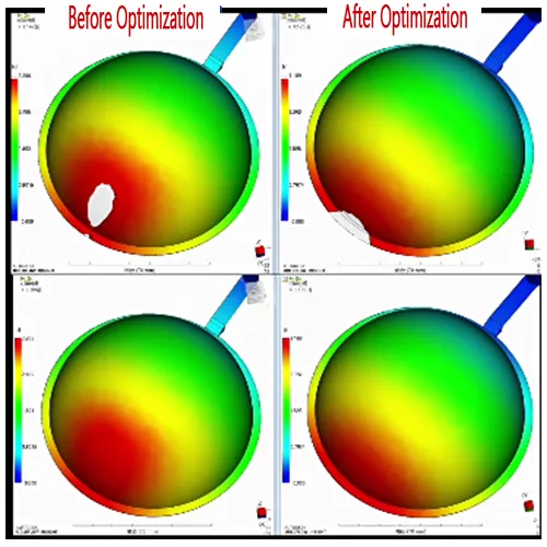
While mold-flow software is highly accurate for filling, packing, and thermal tracking, its birefringence prediction capability is qualitative. The relationship between computed residual stress tensor fields and physical optical retardation depends on stress-optical coefficients that vary by material batch. Simulation effectively identifies high-risk regions. but high-precision applications must validate final performance during initial mold trials.
7. When to Run DFM: Timing Matters as Much as Content
The financial and schedule return on a DFM review is directly tied to when it is executed.
- Too Early: Reviewing a conceptual optical layout or a preliminary lens form without assigned tolerances or concrete material selection yields no actionable engineering data.
- The Optimum Window: DFM must be initiated once the design has achieved:
- Defined lens geometries (radii, center thickness, diameter, and flange profiles).
- Selected or shortlisted resin candidates (e.g., PMMA, PC, or COP).
- Explicit optical performance targets (focal length, transmittance, or wavefront limits).
- Preliminary dimensional tolerances.
- At this stage: the design contains sufficient data for a meaningful mold-flow and stack-up simulation, yet remains flexible enough to accept engineering changes without delaying the project.
- Too Late: (Post-Tooling Start): Executing DFM after mold designs are approved or tool steel has been cut forces findings to be treated as mold tooling modifications rather than design optimizations. Mold rework typically costs 5 to 20 times more than resolving design issues before tooling release.
❌ LATE DFM (AFTER TOOLING BEGINS)
DFM Finding: Gate location induces unacceptable birefringence in the clear aperture.
Resolution: Tooling rework required. Re-machining gate, modifying runner layout, altering cavity inserts.
Impact: $5,000–$20,000 engineering cost | 3–5 weeks schedule delay | Risk of secondary defects.
✅ EARLY DFM (BEFORE TOOLING RELEASE)
DFM Finding: Gate location induces unacceptable birefringence in the clear aperture.
Resolution: Modify gate positioning in the CAD model.
Impact: 2–4 hours of engineering time | Same-day implementation | Zero tooling rework.
8. DFM for Emerging Applications: LiDAR, AR Optics, and Humanoid Robot Vision
Next-generation optical applications introduced in recent years bring complex manufacturing constraints that exceed conventional commercial lens requirements.
Solid-State LiDAR Receiving Optics
LiDAR receiving lenses require a combination of low birefringence for polarization-sensitive detection, tight focal length tolerances for ranging precision, and dimensional stability across automotive thermal profiles (–40°C to 105°C). The engineering challenge is that these requirements drive processing parameters in opposing directions.
COP or COC resins handle the birefringence requirements but feature a narrow processing window. Furthermore, because the clear aperture covers nearly the entire face of a LiDAR receiving lens, the margin for placing gates outside the active zone is minimal. High-aspect film gates or edge gates aligned to specific angular positions relative to the optical axis are frequently required. For AR lenses, birefringence retardation is treated as a primary acceptance criterion rather than a secondary optimization target.
AR Smart Glasses Waveguide Coupling Lenses
Waveguide-based augmented reality displays couple projected images into a planar waveguide element using ultra-precise coupling lenses. Because the polarization state of the light dictates coupling efficiency, any localized birefringence in the coupling lens drops display brightness and uniformity.
For AR lenses, birefringence retardation is treated as a primary acceptance criterion rather than a secondary optimization target. Tooling engineers work backward from these optical limits to optimize gate geometry, gate sizing, and mold temperature controls for volume production.
Humanoid Robot Structured Light Projector Lenses
Structured light 3D sensing systems project precise dot matrices or fringe patterns to map environments for robotic manipulation. Any surface form deviation or internal aberration in the projector lens distorts the pattern, causing depth-calculation errors in the robot’s vision processor.
DFM for these components prioritizes aspheric surface form replication and absolute weld line avoidance across the active aperture. A weld line that passes cosmetic inspection can still cause localized light refraction, disrupting the projected pattern geometry.

9. What ATRMOLD’s DFM Review Process Actually Looks Like
A DFM review for an optical lens project at ATRMOLD follows a defined sequence, producing a written report with specific, actionable findings — not a general assessment of “looks manufacturable.”
Review Inputs & Deliverables:
- Required Documentation: 3D CAD files (STEP or IGES format), optical performance specifications, material selection, and target manufacturing volumes.
- Engineering Evaluation: Verification of gate options relative to clear apertures, wall thickness mapping, shrinkage uniformity profiling, parting line optimization, and tolerance stack-up analysis against proven machine capabilities.
- Simulation Verification: Mold-flow verification covering filling balance, weld line and air trap placement, thermal uniformity, and warpage prediction.
- Engineering Report: A detailed report categorizing all findings by risk level, accompanied by explicit geometry or tooling recommendations.
Turnaround and Engagement Timelines:
- Initial Feasibility Assessment: 24 Hours
- Comprehensive DFM Report with Mold-Flow Simulation: 1–2 Weeks
- Tooling Commitment: The DFM review is available as an independent engineering service; there is no prerequisite to award tooling or production contracts to ATRMOLD.
The full DFM review is offered as a standalone service — you are not required to commit to tooling or production with ATRMOLD to receive a DFM review. For projects where the DFM report identifies issues that require optical redesign, we can recommend approaches but are not the right partner to execute optical system redesign (that’s your optical engineering team’s work). For projects where the DFM report identifies tooling or process-side fixes, we implement those fixes in the mold design and process setup.
If you have an optical lens design ready for DFM review, or if you have a lens that has already gone through tooling and is not hitting specification, our optical design and engineering team can review it. The DFM findings for a project that’s already in trouble are different from an upfront review — but the review is usually faster to produce because the failure mode is already visible, and the fix is often more targeted than starting from a blank design.
Get a Free Optical Lens DFM Review
Submit your lens CAD file and optical specifications. Our engineering team will analyze your geometry, evaluate risks, and deliver an initial feasibility assessment within 24 hours — with no tooling commitment required.
Related Articles & Pages