
Birefringence is a defect that passes visual and dimensional inspection yet still causes application failures because it becomes apparent only when polarization or wavefront performance is evaluated. This guide explains its root causes and how to minimize birefringence before tool fabrication begins.
By: ATRMOLD Engineering Team
July 2026
Reading time: 14 min
Category: Quality Control
- Why Birefringence Fails Lenses That Pass Standard Inspection
- Two Root Causes: Flow-Induced and Thermally-Induced Birefringence
- How to Measure Birefringence: Polarimetry, Retardation, and Wavefront
- Six Prevention Strategies That Work in Volume Production
- Material Selection: The Fastest Route to Low Birefringence
- The Warpage vs. Birefringence Tradeoff: Why You Cannot Optimize Both Simultaneously
- Industry Application Birefringence Sensitivity Guide
- 2026 Applications Where Birefringence Is a Critical Specification
People Also Ask
What is birefringence in optical lenses and why does it matter?
Birefringence is the difference in refractive index experienced by light polarized in two perpendicular directions as it passes through an anisotropic medium. In an ideal isotropic optical material, the refractive index is uniform regardless of polarization direction—light travels through at a constant velocity no matter how it is oriented. A birefringent material exhibits different refractive indices for different polarization directions, splitting polarized light into orthogonal components that travel at different velocities and arrive at the focal plane with a phase difference (retardation) between them.
In injection-molded polymer optical lenses, birefringence is driven by molecular chain orientation and residual stress introduced during the injection and cooling stages of the molding process. It is not a surface defect—it is an internal material state that cannot be detected by visual inspection or standard dimensional metrology. Birefringence manifests as wavefront error in imaging systems, polarization cross-talk in polarization-sensitive sensors, and optical retardation that affects optical path length—all of which degrade system performance while remaining invisible to the naked eye.
1. Why Birefringence Fails Lenses That Pass Standard Inspection
The fundamental challenge of birefringence is that it cannot be detected using standard optical lens inspection methods. A lens with significant birefringence can pass:
- Visual inspection (no surface defects, no cloudiness)
- Dimensional CMM inspection (center thickness, diameter, and radius all within tolerance)
- Transmittance measurement (overall light transmission within specification)
- Scratch-dig surface quality inspection per MIL-PRF-13830B (no scratches or pits)
Yet still fail after integration into the optical assembly because birefringence alters the propagation of polarized light and transmitted wavefront quality—properties that none of the inspections above evaluate.
As a result, detecting birefringence late in the production cycle is exceptionally costly. A batch of lenses that pass incoming quality control, pass first-article inspection, and are integrated into an assembled optical system before the birefringence is detected incurs the full cost of molding, inspection, logistics, and assembly before the defect surfaces. For precision sensing and imaging systems where the failure only becomes apparent during system-level testing, the discovery timeline can be weeks or months post-production.
When Spherical Optical Performance Is Sufficient:
Not every application needs aspheric correction. LED illumination optics, simple collimating lenses, and protective windows operate at conditions where spherical aberration is either negligible or acceptable within the system’s performance budget. Specifying an aspheric design for an application that a spherical lens handles adequately adds mold complexity and cost with no performance return.
2. Two Root Causes: Flow-Induced and Thermally-Induced Birefringence
Flow-Induced
Flow-Induced Birefringence
During cavity filling, polymer chains are sheared and elongated along the flow direction. If these chains freeze in their oriented state before they can relax, they create directional refractive index variations in the solidified lens. Flow-induced birefringence is greatest near the gate, where shear stress is highest, and gradually decreases toward the end of the flow path. It is directly governed by injection speed, melt viscosity, and gate geometry.
Thermally-Induced
Thermally-Induced (Residual Stress) Birefringence
As the lens cools inside the mold cavity, the outer skin solidifies first while the core remains molten. The core contracts as it cools against the rigid skin, generating internal tensile and compressive stresses. This residual stress field produces birefringence through the photoelastic effect—mechanical stress in an optically transparent material changes its refractive index. Thermally induced birefringence is generally more uniformly distributed than flow-induced birefringence and cannot usually be attributed to a single process variable.
Why Gate Placement Determines Birefringence Distribution
The gate is the zone of maximum shear stress—the melt accelerates from the runner into the cavity through the gate restriction, generating the highest molecular orientation in the entire part. Research on plastic optical elements shows that residual stress and birefringence typically peak at or near the gate because of the abrupt geometric transition and rapid increase in melt velocity at the gate entrance.
A gate placed within the clear aperture of a lens deposits maximum birefringence directly in the optical path. A gate placed at the edge of the lens blank, outside the optically active zone, concentrates birefringence at the gate vestige area—which is outside the functional aperture and therefore isolated from the critical light path. Gate placement is the most influential design variable for birefringence control and should be determined during the optical DFM stage rather than left to the toolmaker after the optical design has been finalized.
Gate Angle and Birefringence in Multi-Gate Designs:
For optical elements requiring multiple gates, the angular arrangement of gates relative to the optical axis affects how birefringence contributions from different gates combine. USPTO patent literature indicates that arranging gate angles between 90° and 180° relative to one another suppresses the additive effects of birefringence from multiple gates, with 180° (diametrically opposed gates) providing the most effective cancellation. This is an optical-specific design parameter with no equivalent in standard injection mold DFM guidelines.
3. How to Measure Birefringence: Polarimetry, Retardation, and Wavefront
Crossed-Polarizer Inspection (Qualitative)
The simplest method for detecting birefringence places the lens between two crossed polarizers. An optically isotropic lens transmits no light in this configuration—the crossed polarizers extinguish all transmitted light. A birefringent lens rotates the polarization state of the light passing through it, allowing a portion of the light to pass through the analyzer (the second polarizer). The transmitted light pattern reveals the birefringence distribution across the lens, with high-stress regions appearing as bright or colored fringes. This is a qualitative method: it identifies where birefringence is present and its relative profile, but does not provide a quantitative retardation measurement.
Polarimetric Retardation Measurement (Quantitative)
Quantitative birefringence measurement uses a polarimeter or polarimetric imaging system to measure the optical path difference (retardation) between the two orthogonal polarization components at each point across the lens aperture. Retardation is expressed in nanometers (nm) or fractions of a wavelength (λ). The specification for a precision optical lens might require retardation below 5nm across the full clear aperture—a level that requires quantitative polarimetry to verify and that no visual inspection method can confirm.
Interferometric Wavefront Measurement
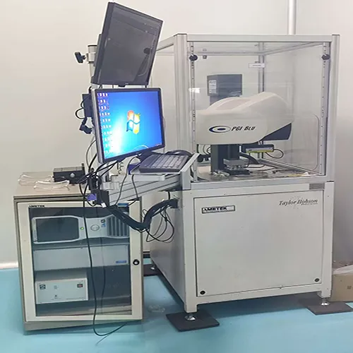
Zygo or Fizeau laser interferometers measure the wavefront transmitted through the lens, which captures the combined effect of surface form error (PV/RMS) and index variations caused by birefringence. Wavefront measurement provides the most direct assessment of how birefringence affects lens performance in its intended application. Rather than evaluating birefringence as an isolated material property, it quantifies its optical impact through transmitted wavefront error (expressed in waves, λ, or RMS wavefront error).
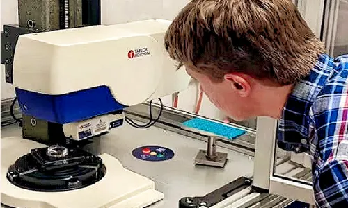
Production Inspection vs. Qualification Testing:
Full polarimetric mapping and wavefront measurement are qualification-level tests—appropriate for first-article approval and periodic audit sampling, not for 100% production inspection at typical cycle times. In volume production, birefringence is controlled through process parameter discipline (SPC on injection speed, mold temperature, packing pressure) rather than 100% measurement. Qualification tests confirm the process window is set correctly; SPC monitoring confirms it is maintained.
4. Six Prevention Strategies That Work in Volume Production
1
Relocate Gate Outside the Clear Aperture
The highest-impact change. Moving the gate from the optical center to the lens flange reduces birefringence in the functional aperture by eliminating the highest-stress zone from the light path.
2
Increase Mold Temperature
Higher mold temperature keeps the polymer molten longer, allowing flow-oriented molecular chains more time to relax before freezing. Scientific Reports research has shown that increasing mold temperature toward the glass transition temperature (Tg) can reduce both peak and average birefringence by up to 50%.
3
Reduce Injection Speed
Lower injection speed reduces the shear rate in the gate and cavity, minimizing flow-induced molecular orientation. The tradeoff is longer fill time—but for optical lenses where birefringence is critical, this tradeoff is almost always necessary.
4
Minimize Packing Pressure
Apply only the packing pressure required to compensate for volumetric shrinkage. Excessive packing pressure forces additional stress into the material during the packing phase, contributing to both flow-induced and thermal birefringence. Use the minimum packing pressure that maintains part weight and surface replication within specification.
5
Specify COP/COC Material
COP and COC exhibit the lowest stress-optic coefficients among common optical polymers—the same level of residual stress produces significantly less birefringence in COP than in PC or PMMA. For birefringence-critical applications, material substitution is often more effective than process optimization alone.
6
Variotherm (Rapid Thermal Cycling) Molding
Variotherm molding rapidly heats the mold cavity above the resin’s glass transition temperature Tg during filling, then cools it rapidly for ejection. The hot filling stage eliminates the frozen layer that captures molecular orientation. Research has shown that at mold temperatures approaching Tg, birefringence can be reduced to near-zero levels.
5. Material Selection: The Fastest Route to Low Birefringence
Not all optical plastics respond equally to the process conditions that cause birefringence. The material property that determines the level of birefringence produced by a given residual stress is the stress-optic coefficient (C)—a material constant that relates applied stress to the resulting change in refractive index. Materials with a lower stress-optic coefficient produce less birefringence for the same level of residual stress.
| Material | Birefringence Sensitivity | Stress-Optic Behavior | Best For | Verdict |
|---|---|---|---|---|
| PC | High Risk | High stress-optic coefficient—even low residual stress produces significant birefringence | Impact resistance — not birefringence-critical optics | Avoid for polarization-sensitive |
| PMMA | Moderate | Lower stress-optic coefficient than PC—wider processing window | LED, display, general imaging optics | Acceptable with process control |
| COP / COC | Very Low Best | Lowest stress-optic coefficient among common optical plastics—near-zero birefringence achievable | Semiconductor inspection, hyperspectral imaging, polarimetric sensors | Preferred for birefringence-critical |
| PS (Polystyrene) | Very High | Negative stress-optic coefficient — birefringence is high and directionally inverted | Limited optical use — generally avoid | Not recommended |
6. The Warpage vs. Birefringence Tradeoff: Why You Cannot Optimize Both Simultaneously
This is one of the most important engineering considerations of birefringence control in injection molding—and the one that many standard DFM guidelines do not address. The process conditions that minimize birefringence tend to increase warpage, and vice versa.
Higher packing pressure reduces shrinkage variation and therefore limits warpage. However, higher packing pressure increases residual stress and therefore drives up birefringence. Lower packing pressure reduces birefringence but allows more differential shrinkage—increasing warpage and dimensional deviation.
The same conflict applies to mold temperature: higher mold temperature reduces birefringence by allowing stress relaxation but extends cycle time and can increase warpage from slower, less uniform cooling. Lower mold temperature reduces warpage risk but spikes flow-induced birefringence.
Consequently, no single process setting exists that minimizes both parameters simultaneously. DFM and process development must establish which specification takes priority—birefringence or dimensional accuracy—and map a process window that meets the primary specification while keeping the secondary specification within its allowable tolerance.

Springer Nature Research Finding:
Research published in Microsystem Technologies using the Taguchi method and grey relational analysis demonstrated that the processing parameters that independently minimize warpage and those that independently minimize residual stress (the source of birefringence) are distinct—and that joint optimization requires a compromise solution that does not fully minimize either variable alone. This finding has direct implications for optical lens process development: establish which variable is more critical to optical performance before freezing the process.
People Also Ask
Why is COP/COC specified for low-birefringence optical applications?
COP (Cyclic Olefin Polymer) and COC (Cyclic Olefin Copolymer) are specified for low-birefringence optical applications because they possess the lowest stress-optic coefficient of all injection-moldable optical plastics. Because the stress-optic coefficient determines how much birefringence a given level of residual stress produces, a lower coefficient yields less birefringence from the same amount of process-induced stress.
COP/COC also features a near-zero moisture absorption rate (below 0.01%), which contributes to exceptional dimensional stability under varying humidity conditions. For precision optical instruments used in laboratory, medical, or field environments where ambient temperature and humidity fluctuate, this dimensional stability prevents the focal length drift and surface form changes that occur in PMMA lenses under humidity cycling.
The practical tradeoff is raw material cost—COP/COC resins carry a significant price premium over PMMA or PC (typically 3–5x per kilogram for optical grades), and have a narrower processing window that requires tighter SPC monitoring. For applications where birefringence below 5nm retardation is a hard requirement—semiconductor inspection optics, hyperspectral imaging windows, polarimetric sensor elements—the additional material cost is justified. For applications where moderate birefringence is acceptable, PMMA is typically preferred for cost-sensitive
7. Industry Application Birefringence Sensitivity Guide
Not every optical application is equally sensitive to birefringence. Sensitivity depends on whether the application utilizes polarized light, evaluates wavefront quality, or relies on the optical path difference between polarization components.
Critical — <5nm retardation required
• Semiconductor Inspection Optics
Wafer inspection and metrology systems use polarized illumination to detect surface features at sub-wavelength scales. Any birefringence in the optical path adds phase noise to the polarimetric signal, masking genuine surface defects. COP/COC is the standard specification for optical elements in semiconductor inspection.
Critical — <5nm retardation required
• Hyperspectral Imaging Lenses
Hyperspectral cameras separate light into dozens of narrow spectral bands using polarization optics and spectral filters. Birefringence in the imaging lens causes polarization cross-talk between spectral channels, corrupting the spectral measurement. Used in precision agriculture, pharmaceutical inspection, and food quality control.
High — <20nm retardation required
• Optical Coherence Tomography (OCT) Systems
OCT medical imaging depends on the coherent interference of low-coherence light to produce depth-resolved tissue images. Birefringence in the imaging optics introduces phase errors that degrade axial resolution and produce imaging artifacts in tissue microstructure images.
High — <20nm retardation required
Agricultural and environmental survey drones use multispectral cameras with polarization filters to measure vegetation indices and water stress. Birefringence in the lens system introduces angular-dependent spectral errors that corrupt the calibrated reflectance measurements used for crop analysis.
High — <20nm retardation required
• Flow Cytometry & Diagnostic Imaging
Clinical flow cytometers use polarized laser illumination to characterize cell populations. Birefringent optical elements scramble polarization states, reducing the signal-to-noise ratio on depolarization channels used to detect cell granularity and morphology.
Medium — <50nm retardation typical
Industrial inspection cameras using structured light or polarized illumination for surface defect detection. Moderate birefringence degrades phase measurement accuracy in structured light systems but is tolerable in standard intensity-based machine vision inspection.
Medium — process-controlled PMMA adequate
Near-infrared camera systems for automotive night vision and driver monitoring. Moderate birefringence reduces NIR image contrast but does not disqualify the lens for most automotive camera specifications. PMMA with the gate outside the clear aperture is typically adequate.
Low — standard process adequate
TIR, secondary, and diffuser optics for LED lighting. Illumination systems are not polarization-sensitive—birefringence does not affect luminous efficacy, beam pattern, or color rendering in any measurable way. A standard PMMA molding process is entirely adequate.
8. 2026 Applications Where Birefringence Is a Critical Specification
Semiconductor Wafer Inspection Systems
The semiconductor industry’s push toward sub-5nm node fabrication has intensified requirements for inspection optics at every stage of wafer processing. Overlay metrology tools, critical dimension scanners, and defect review systems all utilize polarimetric techniques at wavelengths from DUV (193nm) to NIR (850nm+); COP/COC injection-molded elements—where glass is too brittle for vibration-sensitive portable inspection modules—are increasingly specified for intermediate optical relay elements in these systems. Retardation specifications below 2nm are common for elements positioned directly in the polarimetric measurement path.
Hyperspectral Drone Imaging for Precision Agriculture
Precision agriculture drone cameras using hyperspectral imaging to measure crop health, soil moisture, and disease spread are deploying at scale in 2026, driven by food security initiatives in Europe, North America, and East Asia. These cameras use push-broom or snapshot mosaic architectures where spectral separation depends on polarization filters and liquid crystal tunable filters. Birefringence in the objective lens corrupts the angular uniformity of the spectral response, introducing systematic errors in NDVI and other vegetation indices calibrated against known reference standards. COP/COC objectives or PMMA objectives with polarimetric qualification are specified for high-accuracy hyperspectral systems.
Cold-Chain and Food Safety Inspection Vision Systems
Automated food inspection lines—detecting surface contamination, bruising, and foreign material in packaged and fresh food products—increasingly use polarized reflectance imaging to enhance contrast between food surface features and backgrounds. A lens system with inconsistent birefringence across production batches introduces variable polarization sensitivity that causes inspection threshold drift between product lots, requiring frequent recalibration. Low-birefringence lenses with consistent production characteristics reduce calibration frequency and improve inspection reliability in high-speed food processing environments.
Underwater and Marine Optical Systems
Autonomous underwater vehicles (AUVs) for ocean monitoring, subsea pipeline inspection, and marine biology research use polarimetric imaging to penetrate turbid water by filtering out backscattered light—a technique that depends entirely on the polarization purity of the imaging optics. Polycarbonate lenses, despite their high impact strength, introduce polarization errors that degrade scatter rejection. COP-based imaging optics are increasingly specified for AUV vision systems operating in high-turbidity coastal and shallow-water environments.
People Also Ask
How do you test for birefringence in optical lens production?
Birefringence testing in optical lens production uses three methods depending on the required level of data and production stage. Crossed-polarizer visual inspection is the fastest method—placing the lens between two crossed polarizers under white-light illumination. A birefringent lens shows colored or bright stress patterns against a dark background; a non-birefringent lens appears uniformly dark. This is suitable for go/no-go sorting but does not provide quantitative data.
Quantitative polarimetric measurement uses a polarimeter to map optical retardation (in nm) across the lens aperture at defined measurement coordinates. This is used for first-article qualification and periodic sampling in production. For precision optical components with retardation specifications below 10nm, a scanning Mueller matrix polarimeter provides full polarimetric characterization at each point in the aperture map.
Interferometric wavefront measurement (using Zygo or Fizeau interferometers) measures the transmitted wavefront quality of the lens under polarized illumination, providing the combined result of surface form error and birefringence on optical performance. This is the most direct performance-relevant test but requires sophisticated equipment and longer measurement times per part—typically reserved for qualification rather than in-line production sampling.
Birefringence prevention starts at the design stage—gate placement relative to the optical aperture, material selection based on the stress-optic coefficient, and process window definition based on the birefringence vs. warpage tradeoff. By the time birefringence is discovered in an assembled optical system, the mold has been cut and the process has been established. Changes at that stage are expensive.
Our optical design and engineering team evaluates birefringence risk during the DFM review stage—specifically reviewing gate placement relative to the optical aperture, material selection against birefringence sensitivity requirements, and process parameter targets for mold temperature and injection speed. For projects with explicit birefringence specifications, we include polarimetric testing in the first-article acceptance protocol.
Does Your Optical Lens Application Have a Birefringence Specification?
Send us your optical specification including any retardation or wavefront requirements. Our engineering team will recommend the correct material, gate placement, and process approach—and confirm whether polarimetric testing should be included in your first-article acceptance protocol.
Related Articles & Pages