
- What a Light Guide Post Actually Does & What is the Purpose of a Light Guide?
- The Bend Radius Rule: Why a Tight Bend Kills Light Guide Efficiency
- Textured vs. Glossy Surface: Controlling Where Light Exits
- One LED, Multiple Indicators: The Multi-Point Design Problem
- LED Coupling: Flat Entry vs. Shaped Entry
- Why Small Appliance Light Guides Differ from Automotive Ones
- Custom Molded Light Guide vs. Off-the-Shelf Light Pipe
- From DFM to Cleanroom Molding
- Supplier Sourcing Checklist
- Frequently Asked Questions
A single status LED buried inside a massage gun, hair dryer, or coffee maker rarely sits right behind the little glowing dot you see on the outside. Between the LED on the PCB and the visible indicator point, there’s usually a bent, molded light guide post routing that light around internal components — and how well that bend is designed determines whether the indicator looks bright and clean, or dim and inconsistent from unit to unit.
What is a light guide?
At its simplest, a light guide (or light pipe) is a precision molded optical component designed to transport light efficiently from a surface-mount LED source to a designated display interface with minimal flux loss.
This guide covers what actually determines light guide post performance in small appliances: bend radius limits, surface finish control, and the engineering work needed when one LED has to feed more than one visible point.
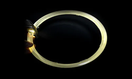
1. What a Light Guide Post Actually Does & What is the Purpose of a Light Guide?
A light guide post transports light from a source to a visible exit point using total internal reflection (TIR), the same fundamental principle covered in more depth in our LED lighting lens guide.
What is the purpose of a light guide in consumer devices?
Unlike a traditional illuminator that shapes a beam for lighting, the core job of a small-appliance light guide post is routing. It channels light from an internal light guide led on the circuit board around spatial constraints to a specific indicator window on the housing — often navigating sharp bends that have everything to do with internal component layout and nothing to do with optimal optics.
2. The Bend Radius Rule: Why a Tight Bend Kills Light Guide Efficiency
Total internal reflection only works when rays strike the internal boundary within a specific critical angle. Bend a light guide too sharply, and light rays that would normally reflect internally hit the surface at an angle steep enough to escape. This causes light leakage out the side of the bend instead of delivering full intensity to the exit face.
Published optical design guidelines offer a practical rule of thumb: for a 1 mm diameter light guide, the minimum bend radius should be roughly 10 mm. Maintaining this 10:1 ratio between bend radius and guide diameter serves as a reliable baseline for most LED Light Guides used in small appliances.
Why this matters at the CAD stage: A bend that looks clean in a 3D CAD model — routed tightly around a battery enclosure or motor housing to save space — can easily violate this critical ratio. Verifying bend radius against guide diameter early in the design phase prevents discovering a dim, underperforming indicator after first-shot T1 samples arrive.
3. Textured vs. Glossy Surface: Controlling Where Light Exits
Surface finish is a functional optical control tool on a light guide, not just an aesthetic detail.
- Glossy / SPI A2 Mirror Finish: Promotes total internal reflection, keeping light bouncing cleanly inside the guide body.
- Textured / Matte Finish: Disrupts TIR, causing light to scatter and exit the material at that specific location.
This functional difference defines how the exit face of a light guide led system is specified: the main body of the guide maintains an optically polished glossy finish to transport light with low loss, while the visible indicator tip features a textured finish to release light as a smooth, diffuse glow rather than a harsh, directional hotspot.
4. One LED, Multiple Indicators: The Multi-Point Design Problem
Appliances featuring multiple status indicators (such as power level, mode selection, or battery charge) sometimes route light from a single LED source across a multi-branch light guide array.
Think of this like a multi-lane highway system: each indicator requires its own dedicated, optically isolated channel within the single molded part. If these channels are not properly isolated, cross-talk occurs. This flaw manifests as secondary indicators glowing faintly even when turned off, or uneven luminance across indicators that ought to look identical.
5. LED Coupling: Flat Entry vs. Shaped Entry
| Entry Design | Coupling Efficiency | Tooling Complexity |
|---|---|---|
| Flat entry surface | Lower — Moderate flux loss at the LED interface | Simpler, lower-cost tooling |
| Shaped Entry Surface (Matched to LED emission profile) | Higher — Captures more of the LED’s angular output | More complex mold geometry, higher initial NRE |
This trade-off represents a practical balance between tooling budget and optical performance, rather than a design oversight. For many low-power LED Light Guides, a simple flat entry surface provides sufficient brightness and remains the most cost-effective choice. However, it becomes an issue when a product brief demands high visual intensity, yet specifies the lowest-efficiency flat entry geometry by default.
6. Why Small Appliance Light Guides Differ from Automotive Ones
Automotive light guides — discussed in detail in our automotive optical lens RFQ guide — are typically longer, edge-lit signature optics engineered to endure extreme thermal cycling, UV exposure, and continuous vehicle vibration.
Light guide posts in small appliances face a completely different operational environment:
- Frequent impact and drop stresses (especially in portable devices like massage guns and power tools)
- Thermal exposure near motors or heating elements (in hair dryers and kitchen appliances)
- Potential moisture or chemical exposure (in bathroom or personal care devices)
Material selection (e.g., optical PMMA vs. shatter-resistant PC) and wall-thickness design must be tailored to these real-world conditions rather than defaulting to automotive-grade assumptions.
7. Custom Molded Light Guide vs. Off-the-Shelf Light Pipe
Off-the-Shelf Light Pipe
- Faster initial procurement for early benchtop proof-of-concept
- Limited to straight or simple 90-degree geometries — rarely fits a compact commercial enclosure
- Generic entry coupling that rarely aligns with your specific LED viewing angle
- Fixed lengths and mounting features, forcing awkward housing compromises
Custom Molded Light Guide Post
- Bend geometry routed around your actual internal layout, validated against bend-radius limits
- Surface finish specified section-by-section to control internal reflection versus light release
- Customized entry optics matched to your specific light guide led for maximum output coupling
- Significantly lower piece-part cost at mass production appliance volumes
8. From DFM to Cleanroom Molding
DFM Review for Bend and Coupling Geometry: Engineering drawings undergo optical DFM analysis to evaluate the bend-radius-to-diameter ratio, entry coupling design, gate location, and draft angles before cutting steel.
Precision Mold Construction: Tooling cavities are machined via precision mold manufacturing, applying polished SPI-A2 finishes and textured surfaces to exact section specifications.
Cleanroom Molding: Production takes place in an ISO-certified cleanroom environment, minimizing particulate contamination on optical surfaces in line with our optical lens injection molding standard.
Cpk-Tracked Verification: Critical optical dimensions and surface figures are monitored using statistical Cpk process controls, as detailed in our optical lens quality control and metrology guide.
9. Supplier Sourcing Checklist
Can you validate our bend geometry against a safe bend-radius-to-diameter ratio during initial DFM?
Can you specify different surface finishes (glossy vs. textured) across distinct sections of the same tool cavity?
For multi-indicator designs, how do you prevent optical cross-talk between adjacent channels within a single molded part?
Can you design a custom entry surface to match our chosen LED’s spatial emission pattern, or advise when a flat entry is sufficient?
Which optical resin grades (PMMA, PC, or COC) do you recommend for our device’s specific drop, thermal, and chemical exposure risks?
Do you track production Cpk data on bend geometry and entry-coupling tolerances?
10. Frequently Asked Questions
Why does my light guide’s indicator look dim even though the LED is bright?
This is usually caused by an excessively tight bend radius relative to the light guide’s diameter, which breaks total internal reflection and causes light to leak internally. A good engineering baseline is a 10:1 ratio between bend radius and guide diameter. Checking this ratio in CAD prior to tooling approval is the most effective way to prevent dim indicators.
How do I control where light exits along a light guide?
Surface finish is the primary mechanism: highly polished (glossy) surfaces maintain total internal reflection to channel light through the post, while textured or micro-structured surfaces scatter light rays and force them to exit. Applying a glossy finish to the guide body and a matte/textured finish to the indicator face is standard industry practice.
Can one LED illuminate multiple indicator points on an appliance?
Yes, by using a multi-channel light guide post where each light path receives a portion of the source output and remains optically isolated within the molded part. Care must be taken during tooling design to prevent optical bleed between adjacent channels, which can cause inactive indicators to glow faintly.
What is the difference between a small appliance light guide and an automotive light guide?
Automotive light guides are typically longer, edge-lit optical rods engineered to withstand extreme ambient temperatures and continuous road vibration. Small appliance light guides are usually shorter, highly compact posts designed to route light around internal mechanics. They must be optimized for impact resistance (drop testing), local motor heat, and cost-effective volume production.
What production volumes are typical for custom light guide post tooling?
Prototype and sampling runs are typically produced in quantities of a few hundred to a thousand units for optical and mechanical fit verification before releasing mass production tooling. Unit costs drop significantly once production reaches standard appliance volume levels.
A light guide post may seem like a simple mechanical component, but ignoring basic optical design rules during layout is a fast track to dim indicators and costly tool modifications. Getting your bend geometry, surface textures, and LED coupling right during the DFM phase ensures a bright, uniform display interface. If you are specifying a custom light guide post for a new device, review the sourcing checklist in Section 9 with your tooling partner before finalizing your design.
Sourcing a Custom Light Guide Post for a New Appliance?
Consult with our optical engineering team to optimize your bend geometry, surface finish specifications, and LED coupling efficiency.
ATRMOLD — Precision Optical Lens Injection Molding & Mold Manufacturing