
MOLD ENGINEERING / TOOLING FUNDAMENTALS
Optical Mold Structure: Why Cavity Precision Defines Lens Quality
A mold’s structure is far more than a housing for the cavity. Insert architecture, alignment tolerances, ejector placement, and venting all sit outside the optical surface itself, yet each can directly contribute to critical defects in the finished lens.
By: ATRMOLD Engineering Team
October 2026
Reading time: 12min
Category: Mold Engineering
- Why Mold Structure Gets More Scrutiny for Optical Lenses
- The Optical Insert: A Mold Within a Mold
- Core-to-Cavity Alignment and Decentration
- Ejector System Placement
- Parting Line Placement
- Venting Without Compromising Optical Performance
- Supplier Sourcing Checklist for Optical Mold Structures
- Frequently Asked Questions
The quality of an optical lens mold depends on more than the finish of its optical surfaces. Core-to-cavity alignment, ejector pin locations, parting line placement, and cavity venting can all affect the final optical performance, even when they do not directly contact the optical clear aperture. These structural details are common sources of molding defects and require closer control than comparable features in standard plastic injection tooling. This guide examines the key structural elements of an optical lens mold and explains why each demands particular attention.
1. Why Mold Structure Gets More Scrutiny for Optical Lenses
On a standard plastic part, a slightly visible ejector pin mark or an inconveniently located parting line may be an acceptable cosmetic compromise. On an optical lens, the same feature can interfere with the optical path. A minor cosmetic issue on a general-purpose plastic housing can become a functional defect in an optical component.
Mold structure is not separate from optical performance. It is one of the foundations of lens quality.
2. The Optical Insert: A Mold Within a Mold
Why Optical Surfaces Are Built as Separate Inserts
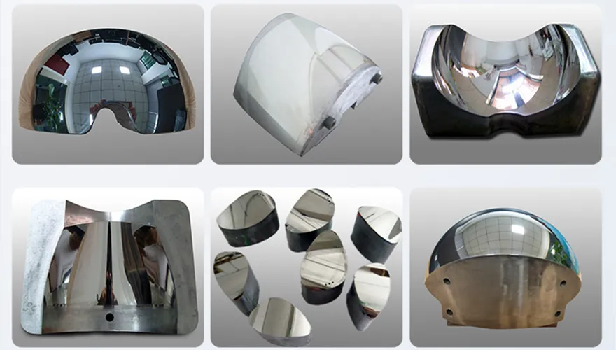
Rather than machining the entire cavity block to an optical-grade finish, precision optical molds often use dedicated inserts to form the optical surfaces. These smaller components are machined and finished separately, then precisely fitted into the larger structural mold base.
In this design, the optical surface and the surrounding mold structure are separate components. This allows each to use suitable tool steels, heat treatments, and surface-finishing methods
What This Modular Approach Actually Buys You
Separating the optical geometry from the structural mold base provides two major engineering advantages:
1. Cost & Material Efficiency: Only the insert requires high-quality optical mold steel, such as ESR-grade stainless steel, suitable for Single-Point Diamond Turning (SPDT) or SPI A-1 mirror polishing, rather than the entire mold base.
2. Serviceability & Maintenance: An optical insert that experiences wear, micro-scratching, or coating degradation can be reworked or replaced independently, without remachining or replacing the complete mold block.
SPI A-1 polish,
independent of base
Optical insert isolated within the structural mold base – different material and finish requirements handled independently
3. Core-to-Cavity Alignment and Decentration
How Injection Pressure Can Deflect Alignment Pins
A potential failure mechanism in optical lens tooling is the deflection of alignment components under injection pressure. As molten resin fills the cavity, the resulting forces can cause core alignment pins or leader pins to flex, potentially shifting or tilting the core axis relative to the cavity center.
This deflection may not be apparent during a static mold inspection. It can become evident only under the injection and packing pressures experienced during the molding cycle.
What Decentration Looks Like in a Finished Lens
When the core’s mechanical axis does not align with the cavity’s optical center, the molded lens can exhibit decentration—a condition in which the optical axis is offset relative to the lens’s geometric reference axis.
In imaging optics, beam-shaping lenses, and sensor covers, decentration can introduce off-axis aberrations, astigmatism, and reduced MTF (Modulation Transfer Function). The cause may lie in structural alignment changes under dynamic pressure rather than in the optical surface finish itself.
CRITICAL TOLERANCE
Critical Tooling Consideration: Guide pin systems, interlocks, and taper block alignments must be designed to withstand the forces generated during mold filling and packing. They should not be evaluated solely in a static, mold-open state. An alignment system that feels tight during manual bench checks may still deflect under molding pressure.
4. Ejector System Placement
Why Ejector Pins Must Remain Clear of the Optical Aperture
Ejector pin marks can result from localized pressure differences, variations in thermal conductivity between the pin and surrounding steel, or minor flash around the pin.
On a cosmetic enclosure, an ejector mark is primarily a visual defect. On an optical surface, it can scatter or obstruct light, reducing optical performance. Ejector pins are therefore positioned outside the active optical clear aperture, typically on mounting flanges, outer rims, or other non-optical features.
Balanced Ejection for Controlled Part Release
To release molded lenses without distorting their optical geometry, precision lens molds use multiple ejector pins arranged to distribute the ejection force evenly. A balanced layout helps reduce localized bending stresses as the lens releases from the core.
Uneven ejection forces can introduce residual stress and physical warpage, adding to the residual stresses already present in the resin after cooling.
5. Parting Line Placement
The parting line—the interface where the core and cavity halves meet—can leave a visible witness line on the molded component. In standard plastic tooling, its location may be driven largely by manufacturing considerations. For an optical lens, the parting line should be positioned outside the optical clear aperture.
A parting line crossing an active optical surface can create a physical discontinuity that scatters light and disrupts wavefront quality. This requirement constrains cavity layout. In multi-cavity tooling, the parting line design must also be consistent across cavities to support uniform part quality.
6. Venting Without Compromising Optical Performance
Effective mold venting allows trapped air and gases to escape as the polymer melt fills the cavity. Inadequate venting can cause short shots, weak weld lines, or dieseling—burn marks caused by compressed gas reaching excessively high temperatures.
Standard tooling practice places shallow vent channels near the end of fill or along ejector pins. For optical components, venting must release trapped gas while keeping vent features outside the optical aperture. Burn marks or gas streaks within the optical path can render a molded lens unusable.
7. Supplier Sourcing Checklist for Optical Mold Structures
When evaluating an injection mold maker or precision optics supplier, use this engineering checklist to assess their structural tooling capabilities:
Insert Architecture & Steel Selection: Does the mold design use modular optical inserts made from suitable ESR-grade stainless steel (e.g., Stavax, S136), separate from the main mold base, to support independent SPDT machining and specialized heat treatment?
Dynamic Alignment & Interlock Rigidity: What structural interlocks, such as side taper blocks or precision-guided alignment systems, are used to limit core-to-cavity movement and tilting under peak injection pressure?
Decentration & Concentricity Control: How does your engineering team measure and control core-to-cavity optical axis alignment, including concentricity tolerances typically (< 0.005mm), during trial sampling and production runs?
Non-Optical Ejection Design: Are ejector pins, gate vestiges, and runner interfaces kept outside active optical zones, on outer mounting flanges or other non-optical features? Is the ejection system designed to distribute force evenly and minimize mechanical stress during release?
Parting Line & Venting Precision: Is the parting line positioned outside the clear aperture, with precision EDM fitting where required to control flash? Are vent channels machined to release trapped gas without compromising optical surfaces?
6. Thermal & Structural Simulation: Are Moldflow and structural deflection analyses performed before machining the tool steel to assess whether clamping and filling pressures could deform the optical insert pockets?
Frequently Asked Questions
Why is the optical surface of a lens mold built as a separate insert?
Building the optical surface as an independent insert allows the manufacturer to use suitable tool steel and specialized surface-finishing techniques, such as SPDT machining and mirror polishing, where needed. It also simplifies maintenance: worn or damaged optical inserts can be reworked or replaced without remachining the structural mold base.
What causes decentration in a molded optical lens?
Decentration occurs when the optical axes of the core and cavity become misaligned or shift relative to the intended lens geometry during molding. One possible cause is core or alignment-component deflection under high injection pressure. The resulting offset between the lens’s optical axis and its geometric reference axis can cause off-axis optical aberrations.
Why can’t ejector pins contact the optical surface?
Ejector pins can leave witness marks, local height variations, or stress whitening on molded plastic. On an optical surface, these defects can scatter light, disturb wavefront quality, and create unwanted reflections, potentially making the lens functionally unacceptable. Ejector pins should therefore be positioned on non-optical features whenever the part design allows.
How does parting line placement impact lens optical performance?
A parting line crossing an active optical zone can create a step or seam that disrupts light transmission. Lens tooling should position the parting line along the outer edge or mounting rim to keep the optical path clear.
None of the structural elements covered here needs to contact the optical surface directly to affect lens quality. Insert architecture, alignment rigidity under injection pressure, balanced ejection, parting line placement, and precision venting are all determined well before the optical surface receives its final finish.
Treating these features as routine tooling details rather than critical elements of optical mold design can increase the risk of lens quality problems. If you’re evaluating a mold design for a new optical lens program, reviewing these points during the design stage can help identify potential issues before steel cutting begins.
Reviewing Mold Structure for a New Optical Lens Program?
Talk to our mold engineering team about insert architecture, alignment tolerances, and ejector placement for your high-precision optical tooling.
ATRMOLD — Precision Optical Lens Injection Molding & Mold Manufacturing