
// PRODUCT SPEC GUIDE — DIFFUSION & BEAM-SHAPING OPTICS
Microlens Array Manufacturing: Pitch, Fill Factor & Sag Height Explained
Custom injection-molded microlens arrays for diffusion, beam homogenization, and backlight applications — the three key parameters that define array geometry and guide specification.
By: ATRMOLD Engineering Team
Sep 2026
Reading time: 8min
Category: Diffusion & Beam-Shaping Optics
| PITCH | 20 µm – 500 µm (application-dependent; ≤200 µm for pattern-invisible diffusers) |
| FILL FACTOR | Up to ~100% with hexagonal or gapless packing; lower with circular packing on a square grid |
| SAG HEIGHT | Typically 1/10 to 1/2 of lens diameter, depending on required optical power |
| ARRAY LAYOUT | Square, hexagonal, or randomized / chirped pitch (for interference suppression) |
| MATERIAL | Optical-grade PMMA, PC, or COC/COP |
| SURFACE PROFILE | Spherical or aspheric (negative conic constant preferred to minimize spherical aberration) |
01 Three Numbers That Define Every Microlens Array
A microlens array specification depends on three interdependent parameters — misjudging their relationship yields a part that passes initial review on paper but underperforms in operation.
PITCH SAG FILL FACTOR = lens aperture area ÷ total array area
Cross-section: pitch (center-to-center spacing), sag height (lens surface depth), and array layout define the lens geometry and packing relationship
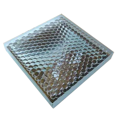
High Fill-Factor Hexagonal Microlens Array for Laser Beam Homogenization
Pitch — the center-to-center distance between adjacent lenslets. A smaller pitch enables finer spatial distribution and can reduce visible patterning, but tighter pitch increases mold insert machining complexity and can accelerate cavity wear over production volumes. For diffuser applications, pitch generally must remain at or below 200 µm to prevent the array pattern from being resolved by the human eye.
Fill factor — the percentage of the array’s total surface area covered by active lens aperture. Gaps between lenslets represent optically dead space — unrefracted light passing through these regions creates stray light and reduces optical efficiency. Hexagonal packing yields a higher fill factor than square packing for round-aperture lenslets.
Sag height — the vertical height of the lens surface above the flat substrate plane. Sag height relative to lens diameter influences optical power; a controlled aspheric profile uses a sag height between 1/10 and 1/2 of the lenslet diameter.
Why this matters for tooling: These three parameters are interdependent. Maximizing fill factor toward 100% while maintaining a sub-200 µm pitch and precise sag height creates significant mold fabrication and demolding challenges. Pushing all three parameters to their extreme limits requires a rigorous DFM analysis prior to steel cutting.
02 Application-Based Selection Matrix
Rather than selecting an arbitrary pitch, define your optical requirements from the application backward:
| Application | Pitch Priority | Fill Factor Priority | Typical Layout |
|---|---|---|---|
| Display / LCD backlight enhancement | Fine pitch, pattern-invisible | High — direct light-output impact | Hexagonal or gapless triangular |
| Laser beam homogenizer | Matched to beam coherence length | High — minimizes stray diffraction | Square or randomized pitch |
| Diffuser plate / privacy film | ≤200 μm, pattern-invisible | Moderate-high | Randomized to suppress interference |
| Sensor / imaging light coupling | Matched to detector pixel pitch | High — coupling efficiency critical | Square, aligned to sensor grid |
| Architectural / signage diffusion | Larger pitch acceptable | Moderate | Square or hexagonal |
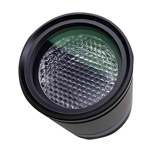
Integrated Microlens Array Lens Assembly for Laser Beam Shaping
03 Frequently Asked Questions
What’s the smallest pitch achievable in injection molded microlens arrays?
Injection molding can produce microlens arrays with pitches down to roughly 20–50 µm, depending on the tool insert fabrication method (such as diamond turning or photolithography/electroforming) and aspect ratio. Finer pitches are typically produced via UV-replication or wafer-level optics rather than direct injection molding.
Does a higher fill factor always mean better performance?
For efficiency-critical applications like backlighting and laser beam homogenization, higher fill factor can reduce the amount of unshaped light passing through dead space, but it does not always result in better overall optical performance. However, for specialized diffusers, randomized pitch and varied fill factor can be intentionally used to suppress moiré patterns and interference fringes.
Can sag height and pitch be specified independently?
Not entirely — sag height is geometrically constrained by pitch, lens aperture, and the desired fill factor. A lenslet cannot exceed its available geometric rise within its allocated footprint without interfering with adjacent lenslets. Optical design requires iterating pitch, sag height, and radius of curvature together to achieve the target optical power.
What causes lens-to-lens variation across a molded array, and does it matter?
Tool wear, non-uniform mold temperature distribution, and packing-pressure gradients across large cavity surfaces can cause geometric variations. For homogenization optics, spatial uniformity across the array is critical — dimensional variations between lenslets can directly contribute to output non-uniformity.
04 Manufacturing Capability
Pitch, fill factor, and sag height evaluated concurrently against moldability, tool machining, and demolding draft constraints prior to tooling.
Tool steel and nickel inserts machined with ultra-precision single-point diamond turning or micro-EDM to maintain sub-micron form accuracy across the full array.
Class 10,000 / ISO 7 cleanroom molding to minimize airborne particulate contamination on fine-pitch optical surfaces.
Array Uniformity Verification
Lens-to-lens dimensional accuracy and fill-factor consistency validated through production Cpk analysis, not single-point inspection.
05 Supplier Checklist
Can you machine mold inserts to our required pitch and fill factor combination, and identify DFM risks before tooling?
What lens-to-lens uniformity and profile accuracy Cpk data can you provide across the full array area?
Can you supply array layouts (square, hexagonal, randomized) tailored to suppress optical interference?
What optical polymers (PMMA, PC, COP/COC) do you recommend to achieve the target sag height and minimize birefringence?
What ISO cleanroom class is used for molding and packaging?
Do you track continuous Cpk data for pitch, sag, and fill-factor consistency across production volumes?
A microlens array’s performance depends on the interaction among pitch, fill factor, and sag height. Specifying all three parameters around system-level optical requirements — rather than requesting generic “fine pitch, high fill factor” defaults — helps ensure the molded part meets its optical requirements in production.
Specifying a Custom Microlens Array?
Consult our optical engineering team regarding pitch, fill factor, and array layout optimization for your diffusion or beam-shaping application.
ATRMOLD — Precision Optical Lens Injection Molding & Mold Manufacturing
One comment
Comments are closed.
[…] Microlens Array Manufacturing: Pitch, Fill Factor & Sag Guide […]