
ACTIVE NIR ILLUMINATION OPTICS
Security IR Illuminator Lens Manufacturing: 850nm/940nm Design Guide
Custom TIR and collimating lenses for CCTV IR illuminator arrays — covering wavelength selection, beam-angle matching to the camera field of view, and why this active-illumination optic presents fundamentally different material requirements from a passive PIR sensor window.
- What Is a Security IR Illuminator Lens?
- 850nm vs. 940nm: Wavelength Selection and Lens Design Impact
- Beam Angle Matching: Why Illuminator Optics Must Match Camera FOV
- Material Selection: Why This Isn’t the Same Problem as a PIR Window
- Multi-LED Array Optics and TIR Lens Design
- Eye Safety and Photobiological Compliance Considerations
- Outdoor Durability Requirements for Illuminator Optics
- Custom Molded Illuminator Lens vs. Off-the-Shelf Optic
- From DFM to Cleanroom Molding
- Supplier Sourcing Checklist
- Frequently Asked Questions
A night-vision security camera doesn’t see in the dark on its own — it relies on an IR illuminator to flood the scene with near-infrared light the camera’s sensor can detect but the human eye can’t. If the illuminator lens is improperly specified, the issue appears directly in the recorded footage: a blown-out center hotspot with dark, unusable edges, a maximum range falling well short of specification, or a faint visible red glow when the application requires covert operation.
This guide covers what determines security IR illuminator lens performance: wavelength selection between 850nm and 940nm, beam-angle matching to the camera’s actual field of view, and material selection specific to active NIR illumination — which, despite both involving “infrared” terminology, represents a fundamentally different manufacturing discipline than the passive PIR sensor windows covered in our related guide.
1. What Is a Security IR Illuminator Lens?
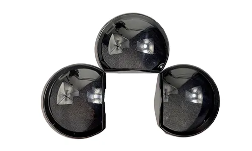
A security IR illuminator lens is the optical component placed over one or more near-infrared LEDs to shape and direct output into a controlled beam that illuminates a scene for a night-vision camera. Also referred to as a CCTV IR lens, infrared illuminator optic, or night-vision LED lens, it performs the same non-imaging light-shaping function as the TIR and collimating optics covered in our LED lighting lens guide — the primary difference being that it shapes near-infrared output for camera sensors rather than visible light for human perception.
2. 850nm vs. 940nm: Wavelength Selection and Lens Design Impact
Two wavelengths dominate security IR illumination, and wavelength selection affects both illumination performance and the covert-versus-visible tradeoff required by end users:
| Wavelength | Range Performance | Visibility | Typical Fit |
|---|---|---|---|
| 850nm | Roughly 30–50% longer range than 940nm at equal power, due to higher silicon sensor quantum efficiency | Faint red glow visible up close | General perimeter and area surveillance where covert operation isn’t required |
| 940nm | Shorter range and dimmer image at equal power | Fully invisible to the naked eye | Covert installations, facial-recognition or biometric cameras aimed at people |
Because an optic optimized for 850nm operation is not automatically optimized for 940nm performance, the optical design — not just the LED selection — must be specified for the exact target operating wavelength.
3. Beam Angle Matching: Why Illuminator Optics Must Match Camera FOV
One of the most common field-performance issues in IR illumination is geometric mismatch rather than insufficient optical power. If the illuminator’s beam angle is narrower than the camera’s field of view (FOV), the resulting image exhibits a bright center hotspot flanked by dark, unexposed regions. Conversely, if the illuminator beam is wider than the camera’s FOV, emitted energy is wasted illuminating areas outside the camera sensor’s capture area, degrading effective illumination range.
Design implication: The illuminator lens beam angle must be engineered to match the specific field of view of the paired camera, rather than selected from generic wide- or narrow-beam optic options. High-power multi-LED arrays frequently employ individual lenslets per LED die to shape and overlap the composite beam pattern precisely across the target FOV
4. Material Selection: Why This Isn’t the Same Problem as a PIR Window
A common point of confusion: Is that both a security IR illuminator lens and a PIR motion sensor window are categorized as “infrared” optics, yet they operate in entirely different spectral bands and require different material systems. See our guide to custom IR plastic optics and PIR windows for passive thermal sensing.
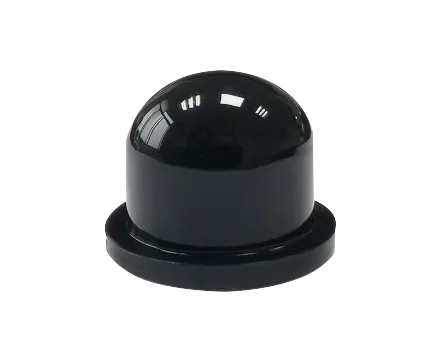
An 850nm or 940nm IR illuminator operates in the near-infrared (NIR) band. Because NIR wavelengths are close to the visible spectrum, standard optical polymers such as optical-grade PC, PMMA, and COC/COP can provide high transmittance at these wavelengths. A passive PIR sensor, by contrast, operates in the far-infrared (LWIR/thermal IR) band around 8–14 microns, where standard optical plastics generally exhibit very low transmittance, requiring specialized materials such as high-density polyethylene (HDPE) or other IR-transmissive materials.
In manufacturing terms: A security IR illuminator lens utilizes standard optical injection molding processes and TIR design methodologies, whereas a PIR sensor window requires completely different tooling and polymer processing techniques.
5. Multi-LED Array Optics and TIR Lens Design
High-power illuminators commonly utilize multi-emitter IR LED arrays to achieve higher radiant intensity and uniform beam distribution across the target scene. This architecture influences optical design directly:
- Individual TIR lenslets for each LED can be integrated into monolithic array plates, designed to blend adjacent emission patterns smoothly without generating localized intensity peaks or dark bands.
- Facet geometry and gate placement require strict control — positioning an injection gate within or too close to an active optical zone can introduce residual stress and flow-line defects that disrupt beam uniformity.
- Thermal proximity in high-density LED arrays necessitates high-temperature optical polymers or thermally stabilized resin grades, particularly for long-range illuminators operating at continuous maximum drive current.
6. Eye Safety and Photobiological Compliance Considerations
Because near-infrared light may not trigger the same natural aversion response as visible light, high-radiance IR illuminators — especially those deployed in facial-recognition or access-control applications — may require photobiological safety evaluation under standards such as IEC 62471. Depending on the device configuration and radiance level, low-power LEDs may fall within Exempt or Risk Group 1 classifications, while higher-output arrays may require formal photobiological safety assessment.
Compliance certification for the finished device remains the responsibility of the OEM manufacturer. As an optical component mold maker, our role is providing verified spectral transmittance, surface quality, and spatial beam distribution data to support the OEM’s downstream photobiological safety compliance testing.
7. Outdoor Durability Requirements for Illuminator Optics
Most security IR illuminators are outdoor-rated components, typically specified to IP66 or IP67 sealing standards, and share the same UV and thermal cycling exposure profile as the outdoor camera lenses covered in our security and surveillance lens category — UV-stabilized material grades and sealed housing integration are standard requirements, not optional upgrades, for any illuminator expected to hold performance over a multi-year outdoor service life.
8. Custom Molded Illuminator Lens vs. Off-the-Shelf Optic
Off-the-Shelf Illuminator Lens
- Faster initial sourcing for early prototyping
- Fixed beam angle — may not match your specific camera’s FOV
- Generic optical performance, not specifically optimized for your 850nm or 940nm LED
- Standard array spacing that may not fit a custom PCB layout
Custom Molded IR Illuminator Lens
- Beam angle engineered to match your paired camera’s actual FOV
- Transmittance optimized for your specific wavelength (850nm or 940nm)
- Lenslet array layout matched to your PCB and LED placement
- Unit cost can improve significantly at higher production volumes
9. From DFM to Cleanroom Molding
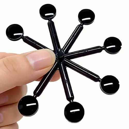
DFM Review for Beam Performance. Drawings are reviewed through optical engineering analysis, including beam-angle simulation against your target camera FOV, before tooling begins.
Precision Mold Construction. Cavities are built through precision mold manufacturing, with lenslet array geometry verified before production release.
Cleanroom Molding. Production is carried out in a controlled manufacturing environment consistent with the requirements of the optical lens injection molding process.
Wavelength-Specific Verification. Transmittance is verified at the actual wavelength in use (850nm or 940nm), not a generic visible-light spec.
10. Supplier Sourcing Checklist
Can you optimize optical transmittance and any required coating for our specific operating wavelength — 850nm or 940nm?
Can you simulate and match beam angle to our paired camera’s actual field of view before tooling?
Do you support multi-LED lenslet array layouts matched to our PCB design?
What material grades and UV stabilization do you offer for outdoor IP66/IP67-rated installations?
Can you provide beam-angle and transmittance data to support our own photobiological safety assessment?
What controlled-environment or cleanroom conditions do you use for optical lens production?
Frequently Asked Questions
Why does my security camera’s night vision image have a bright center and dark edges?
This “hotspot” pattern is almost always a beam-angle mismatch — the illuminator’s beam is narrower than the camera’s field of view, concentrating light in the center while the edges of the frame go dark. Matching the illuminator lens beam angle to the paired camera’s actual FOV during optical design resolves this.
Should I use 850nm or 940nm for my security camera IR illuminator?
850nm can provide roughly 30–50% longer range than 940nm at equal power because of higher silicon sensor quantum efficiency, but it may produce a faint visible red glow at close range. 940nm is generally invisible to the naked eye, making it suitable for covert installations, although this typically comes at the cost of shorter range and reduced image brightness at equal optical power.
Is an IR illuminator lens the same as a PIR sensor lens?
No, despite both being called “infrared” components. An IR illuminator operates in the near-infrared band (850/940nm) and uses standard optical plastics like PC or PMMA. A PIR motion sensor detects far-infrared thermal energy in the 8–14 micron band and typically requires specialized IR-transmissive materials, since standard optical plastics generally provide very low transmittance in that wavelength range. See Section 4 for the full comparison.
Do IR illuminators need eye safety certification?
Higher-power illuminator arrays, particularly those aimed at areas where people are present, are typically assessed against photobiological safety standards such as IEC 62471. This assessment and any related certification is the responsibility of the device OEM; we support it by providing accurate optical performance data on the lens component itself.
What production volumes are typical for custom IR illuminator lens tooling?
Prototype and beam-pattern validation quantities may range from small batches to hundreds of units before full production tooling is released, depending on the manufacturing method and program requirements. Unit costs improve significantly at production illuminator volumes compared to prototype-stage runs.
A security IR illuminator lens may appear straightforward — simply an optical component positioned over an LED array — but beam-angle matching, wavelength-specific optical performance, and outdoor durability directly affect whether the camera delivers usable night-time footage. If you’re specifying illuminator optics for a new camera or lighting program, the questions in Section 10 are worth working through with your manufacturing partner before tooling begins.

ATRMOLD Optical Engineering Team
Precision Optical Lens Injection Molding & Mold Manufacturing
This guide was prepared by ATRMOLD’s optical engineering team, who work daily on DFM review, mold cavity design, and cleanroom production for non-imaging optical components — including TIR and collimating lenses for LED and NIR illumination systems. Technical guidance in this article is based on our production experience and applicable optical and surveillance engineering references.
Sourcing a Custom Security IR Illuminator Lens?
Talk to our optical engineering team about beam-angle matching, wavelength-specific transmittance, and outdoor-rated material selection for your camera or lighting program.
ATRMOLD — Precision Optical Lens Injection Molding & Mold Manufacturing