
PROJECTOR & LIGHT ENGINE OPTICS
Projector Illumination Lens & Light Engine Optics Manufacturing
Custom condenser lenses, TIR collimators, and light-pipe optics for LED and laser projector light engines — how illumination-side optics are engineered for etendue-matched coupling efficiency, and why they require a different design approach from the projection lens that forms the image on screen.
- What Is a Projector Illumination Lens?
- Light Engine Architecture: Where the Illumination Lens Fits
- TIR Collimator & Condenser Lens Design for LED/Laser Sources
- Material Selection for High-Brightness Light Engines
- Etendue and Coupling Efficiency: Why Lens Geometry Determines Brightness
- Tolerance & Consistency Requirements for Light Engine Optics
- Custom Molded Optics vs. Off-the-Shelf Collimators
- From DFM to Cleanroom Molding
- Supplier Sourcing Checklist
- Frequently Asked Questions
Every projector, from a pocket DLP unit to a large-venue laser projector, splits its optical system into two fundamentally different tasks. One collects light from an LED or laser source and shapes it into a controlled, uniform beam directed toward the display panel. The other takes the image formed at that panel and projects it onto a screen in focus. These are engineered as separate optical subsystems for a reason — sourcing teams that treat them as the same component risk selecting a supplier without the required optical manufacturing capabilities.
This guide covers the first subsystem: illumination-side optics — condenser lenses, TIR collimators, and light-pipe components — including material selection for the extreme thermal loads near a high-brightness LED or laser source, and the etendue-matched design work that determines how much of that raw light actually reaches the screen as usable brightness.
Scope note: This guide covers illumination-side optics (condenser and collimator lenses). It does not cover the multi-element projection lens that forms and focuses the final image — that’s a distinct precision imaging optics discipline with its own MTF and distortion requirements, outside the scope of what’s discussed here. See the FAQ for more on this distinction.
1. What Is a Projector Illumination Lens?
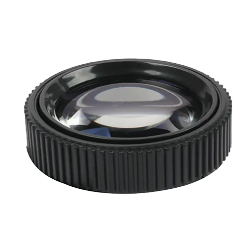
A projector illumination lens is the optical component sitting between the light source (LED or laser) and the display panel (DMD or LCD), responsible for collecting divergent light and shaping it into a controlled, uniform beam. The two most common types are:
• TIR (total internal reflection) collimator lens — captures the wide-angle emission from an LED die and redirects it into a narrower, more usable beam through internal reflection.
• Condenser lens — concentrates the collimated or partially shaped beam further, focusing it onto the next stage of the light engine, typically a fly-eye lens array or light tunnel that homogenizes the beam before it reaches the display panel.
Neither component forms an image. Their entire function is to move light efficiently and uniformly from source to panel — which is why they’re designed and manufactured as non-imaging optics, distinct from the projection lens discussed in the scope note above.
2. Light Engine Architecture: Where the Illumination Lens Fits
A typical LED or laser projector light engine follows this general optical path:
LED/laser light source
TIR collimator lens — captures and narrows the raw emission angle
Condenser lens — concentrates the beam toward the homogenizing stage
Fly-eye lens array / light pipe — homogenizes beam uniformity across the panel
DMD or LCD display panel — forms the image
Projection lens (imaging optics) — projects the formed image onto the screen, outside this guide’s scope
Steps 2 through 4 are where injection-molded illumination optics do their work. Published optical engine research on compact DLP projectors reports illumination-side light efficiency of roughly 50% with panel uniformity above 95% in well-designed systems — figures that depend directly on how closely the collimator and condenser lens geometry matches the LED source’s emission characteristics.
3. TIR Collimator & Condenser Lens Design for LED/Laser Sources
Design accuracy for illumination-side optics centers on matching lens geometry to the light source’s specific emission pattern:
- Facet and groove geometry in a TIR collimator determines how much of the LED’s hemispheric emission is actually captured — Tip radii and facet depth directly affect scattering losses, reducing usable brightness even when the other optical components perform as specified.
- Beam angle matching between collimator and condenser — a mismatch between stages wastes captured light before it ever reaches the homogenizing optics.
- Thermal proximity to the source — High-brightness LED light engines can operate at current densities in the range of several amps per square millimeter, placing the illumination lens close to a high-heat source, which is central to the material discussion in Section 4.
4. Material Selection for High-Brightness Light Engines
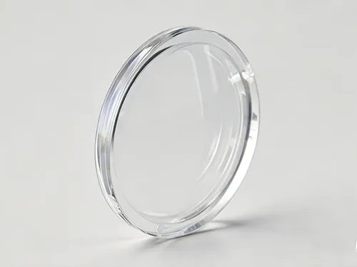
Illumination optics sit closer to the light source — and therefore closer to operational heat — than most other LED lens applications. Material selection has to account for that directly.
| Material | Thermal Suitability | Typical Fit |
|---|---|---|
| Optical PMMA | Suitable below ~80°C; used widely for TIR collimator geometry | Lower-brightness, cost-sensitive light engines |
| Optical PC | Higher softening point than PMMA; gradual yellowing risk under sustained heat | Mid-brightness light engines with moderate thermal load |
| Optical Silicone (LSR) | Stable well beyond 100°C with minimal yellowing over extended exposure | High-brightness LED and laser light engines with sustained close-proximity heat |
For the same thermal-yellowing considerations covered in our broader guide to LED lighting lens injection molding, the highest-brightness projector light engines — particularly compact designs where the collimator sits close to a high-current-density LED or laser diode — increasingly favor optical silicone for components nearest the source, while PMMA or PC are used for downstream stages where thermal exposure is lower.
5. Etendue and Coupling Efficiency: Why Lens Geometry Determines Brightness
In illumination engineering, etendue describes the fundamental limit on how much light can be coupled from a source into an optical system without loss — matching the collimator and condenser geometry to the source’s etendue and the display panel’s downstream acceptance angle determines how much of the LED’s emitted light reaches the screen as usable brightness.
Why this matters for sourcing: Two light engines using the identical LED source can differ meaningfully in screen brightness purely because of how well the illumination lens geometry is matched to that source’s etendue and the panel’s acceptance angle downstream — a design and tooling accuracy question, not just a materials question.
6. Tolerance & Consistency Requirements for Light Engine Optics
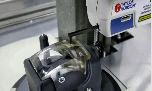
Facet geometry, concentricity to the LED package, and surface finish all directly affect coupling efficiency, which is why Cpk tracking on these specific features — not just overall part dimensions — is the meaningful quality metric for illumination lens production, consistent with the approach detailed in our optical lens quality control and metrology guide. A lens that is dimensionally within tolerance but has facet tip radii drifting between cavities can still produce measurable unit-to-unit brightness variation.
7. Custom Molded Optics vs. Off-the-Shelf Collimators
Off-the-Shelf Collimator/Condenser
- Faster initial sourcing for early prototyping
- Generic geometry not matched to your specific LED/laser emission pattern
- Fixed material grade regardless of your light engine’s actual thermal profile
- Coupling efficiency left unoptimized for your source
Custom Molded Illumination Optics
- Facet and beam geometry engineered around your specific source’s etendue
- Material grade matched to your light engine’s actual thermal environment
- Facet-level Cpk tracking specific to your part
- Unit cost decreases significantly at production light-engine volumes
8. From DFM to Cleanroom Molding
DFM Review for Coupling Efficiency. Drawings are reviewed through optical design engineering analysis for facet geometry, beam-angle matching, and gate placement before tooling begins.
Precision Mold Construction. Cavities are built through precision mold manufacturing, with facet-surface accuracy verified before production release.
Cleanroom Molding. Production is carried out in a controlled cleanroom, consistent with our broader optical lens injection molding process.
Thermal-Grade Verification. Material selection is validated against the light engine’s actual operating temperature near the LED or laser source, not only room-temperature specifications.
9. Supplier Sourcing Checklist
Can you engineer facet and beam geometry around our specific LED or laser source’s emission pattern and etendue?
What material grades do you offer, and how do you determine the right one for our light engine’s thermal profile?
Do you track Cpk data on facet-level features, not just overall part dimensions?
Can you validate coupling efficiency before tooling is released?
What cleanroom classification do you produce in?
Can mounting geometry be matched to our existing light engine housing without rework?

Frequently Asked Questions
Do you manufacture the projection lens that forms the image on screen?
No. This guide and our current capability cover illumination-side optics — condenser lenses, TIR collimators, and light-pipe components that shape and direct raw light toward the display panel. The projection lens itself is a multi-element imaging optical system with its own MTF and distortion requirements, and is a distinct discipline from the non-imaging illumination optics described here.
What’s the difference between a collimator lens and a condenser lens in a projector?
A collimator lens captures the wide-angle divergent light from an LED or laser source and narrows it into a more directional beam. A condenser lens then further concentrates that beam toward the next stage of the light engine — typically a fly-eye array or light pipe that homogenizes the illumination before it reaches the display panel.
Why does screen brightness vary between light engines using the same LED source?
Rightness differences with an identical LED source usually result from how closely the illumination lens geometry is matched to the source’s etendue and the display panel’s acceptance angle. Facet tip radii, beam-angle matching between collimator and condenser stages, and overall coupling efficiency all affect how many raw lumens actually reach the screen.
What material should I use for a high-brightness LED or laser projector illumination lens?
Optical silicone is generally the more reliable choice for illumination optics sitting close to a high-current-density LED or laser source, given its stability well beyond 100°C. PMMA and PC remain suitable for lower-brightness engines or downstream stages further from the direct heat source.
What production volumes are typical for custom projector illumination lens tooling?
Prototype and optical validation batches are typically produced in the hundreds of units to confirm coupling efficiency and thermal performance before committing to full production tooling. Unit costs improve significantly at light-engine production volumes compared to prototype-stage runs.
Projector brightness and uniformity depend on the precision of the illumination optics — matching lens geometry to the source’s etendue, controlling facet tolerances to minimize unit-to-unit brightness variation, and selecting materials that withstand sustained exposure to high heat. If you’re specifying condenser or collimator optics for a new light engine program, review the questions in Section 9 with your manufacturing partner before tooling begins.
ATRMOLD Optical Engineering Team
Precision Optical Lens Injection Molding & Mold Manufacturing
This guide was prepared by ATRMOLD’s optical engineering team, which works daily on DFM review, mold cavity design, and cleanroom production for non-imaging optical components — including TIR collimators, condenser lenses, and light-pipe optics for LED and laser illumination systems. Technical claims in this guide are based on our production experience combined with published optical engineering research cited throughout.
Sourcing Illumination Optics for a Projector Light Engine?
Talk to our optical engineering team about TIR collimator design, thermal-grade material selection, and etendue-matched optics for your light engine program.
ATRMOLD — Precision Optical Lens Injection Molding & Mold Manufacturing