
Custom LED lens and TIR secondary optics manufacturing for luminaires, flashlights, grow lights, and specialty illumination — why thermal yellowing, not scratch resistance, is the failure mode that actually shortens LED lens lifetime, and how material choice determines when it happens.
By: ATRMOLD Engineering Team
August 2026
Reading time: 10 min
Category: LED Illumination Optics
- What Is an LED Lens (Secondary Optics)?
- Why Secondary Optics Determine LED System Efficiency
- The Real Failure Mode: Thermal Yellowing and the Zone of Catastrophic Failure
- Material Selection for LED Lens Applications
- Design Considerations: TIR Geometry, Beam Angle, and Gate Placement
- Application-Specific Requirements Across LED Lighting Categories
- Custom Molded LED Lens vs. Off-the-Shelf Optic
- From DFM to Cleanroom Molding: How an LED Lens Program Runs
- Supplier Sourcing Checklist
- Frequently Asked Questions
An LED chip on its own emits light across a wide angle — a broad distribution unsuitable for most targeted illumination applications. The secondary optic, or LED lens, converts that raw emission into a controlled beam: a tight spot for a flashlight, a wide, uniform wash for a downlight, or a precisely distributed pattern for a street light. Selecting or molding the lens improperly can cause the system to miss its target beam angle or glare-control requirements, or—more frequently than expected—experience early photothermal yellowing that reduces lumen output long before the LED chip itself degrades.
This guide covers what actually determines LED lighting lens performance and operating lifespan: TIR (total internal reflection) lens design, material selection for thermal and UV stability, and the critical failure mode most sourcing teams fail to specify against until field returns occur.
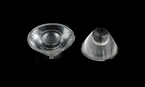
1. What Is an LED Lens (Secondary Optics)?
An LED lens — commonly called secondary optics in lighting engineering, distinct from the LED package’s primary encapsulation — is the molded optical component placed over an LED chip to redirect and shape its light output. The three main design families include:
- TIR (total internal reflection) lenses — capture and redirect a high proportion of the LED’s light through internal reflection and refraction, delivering optical efficiency above 90% without a reflective coating or mirror.
- Collimating lenses — focus divergent LED light into a narrow, controlled beam, used in flashlights, spotlights, and long-throw area lighting.
- Diffuser and light-guide optics — spread and even out light output for glare-free, uniform illumination in general lighting fixtures.
Whatever the design family, the underlying manufacturing challenge remains identical: maintaining precise optical geometry — often concentric grooves or freeform curved surfaces — in a component sitting in close proximity to a high-heat source, shot after shot, across a full production run.
2. Why Secondary Optics Determine LED System Efficiency
A well-designed TIR lens achieves optical efficiency above 90%, allowing the fixture to retain nearly all the light emitted by the LED chip. A poorly designed or defectively molded lens loses efficiency through internal scattering, uncontrolled Fresnel reflections, and stray light—forcing the fixture to use a higher-wattage LED to achieve the target lumen output and increasing both unit cost and thermal load.
Beam angle control is equally critical for photometric compliance and performance: glare issues, inconsistent illuminance across a target surface, or failure to meet specified beam distributions frequently trace back to secondary optics mismatched to the LED’s emission profile — not to the LED chip itself.
3. The Real Failure Mode: Thermal Yellowing and the Zone of Catastrophic Failure
Most sourcing discussions for LED lens materials focus on initial transmittance and unit cost. However, the metric that actually predicts field lifespan is photothermal yellowing behavior — which manifests differently depending on polymer selection.
Polycarbonate (PC) LED lenses subjected to sustained photothermal load can exhibit a two-stage degradation process documented in industry reliability testing. In the initial stage, the yellowness index (YI) rises gradually — a subtle color shift that often stays within acceptable limits during standard lumen maintenance testing. The primary risk lies in the second stage: once YI crosses a material-specific threshold, known as the Zone of Catastrophic Failure (ZCF), the lens darkens rapidly, with severe cases experiencing thermal deformation or melting. Because this threshold can vary between resin lots, two lenses molded from nominally identical PC grades can exhibit significantly different service lives.
PMMA demonstrates a distinct thermal response: it generally maintains optical stability below approximately 80°C, but above this threshold, degradation can occur more abruptly than the progressive yellowing observed in PC.
Why this matters for sourcing: A supplier that provides only room-temperature transmittance and initial color coordinates offers no insight into how the component will perform along its thermal degradation curve. Always request photothermal aging data at your fixture’s actual operating temperature rather than relying solely on ambient optical specifications.
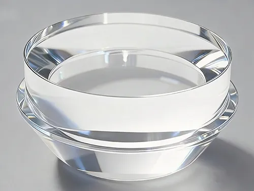
4. Material Selection for LED Lens Applications
| Material | Thermal Behavior | UV / Yellowing Resistance | Typical Fit |
|---|---|---|---|
| Optical-Grade PC | Higher softening point (~130°C); gradual YI rise, then abrupt ZCF failure | Yellows under prolonged UV exposure | Cost-driven indoor fixtures with moderate thermal load |
| Optical-Grade PMMA | Stable below ~80°C; abrupt failure above that threshold, minimal warning | Yellows under prolonged UV exposure | TIR lenses in lower-heat applications; widely used for standard beam optics |
| Optical-Grade Silicone (LSR) | Stable to 150°C over extended aging; higher CTE requires dimensional compensation | No significant yellowing observed after extended outdoor UV exposure | High-power, high-temperature, or outdoor fixtures near the LED junction |
| COC/COP | Good dimensional stability under moderate thermal cycling | Good long-term optical stability | Precision beam optics where low birefringence matters |
Optical silicone’s higher coefficient of thermal expansion (CTE) means that a TIR lens designed for a tight beam angle can undergo greater dimensional expansion during operation. This dimensional expansion must be accounted for during optical tool design—not through material selection alone—to minimize beam-angle drift between cold start and steady-state thermal equilibrium.
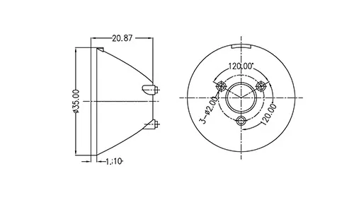
5. Design Considerations: TIR Geometry, Beam Angle, and Gate Placement
• Total internal reflection geometry — the critical angle relationship between the internal optical surfaces and the LED emission profile determines light capture efficiency versus stray light loss.
• Beam angle / FWHM (full width at half maximum) specification — the working distance and target illuminance dictate whether a narrow spot, medium flood, or wide wash optic is required.
• Gate placement relative to the optical zone — positioning an injection gate too close to an active optical surface can introduce flow lines and stress birefringence that manifest as visible hot spots, rings, or distortion in the projected beam.
6. Application-Specific Requirements Across LED Lighting Categories
| Application | Primary Requirement | Material Consideration |
|---|---|---|
| Street & Area lighting | Wide, uniform beam distribution; long outdoor UV exposure | Silicone or UV-stabilized PC/PMMA |
| Downlight / Spotlight fixtures | Tight beam angle control, minimal glare | PMMA TIR lens, moderate thermal load |
| Portable / Flashlight optics | High collimation efficiency in a compact footprint | PC for impact resistance, or PMMA for optical clarity |
| Horticultural / Grow lighting | Sustained high-power operation, close LED proximity | Optical silicone for high-temperature stability |
| Medical & Dental curing lights | Precise collimation at close working distance, repeated thermal cycling | Optical silicone or high-temperature PC, application-specific validation by the OEM |
7. Custom Molded LED Lens vs. Off-the-Shelf Optic
Off-the-Shelf LED Optic
- Fast sourcing for prototyping or low-volume fixtures
- Fixed beam angle — may not match the specific LED emission pattern
- No control over polymer thermal grade or photothermal aging behavior
- Generic mounting footprint that may require housing redesign
Custom Molded LED Lens
- TIR geometry engineered around your specific LED light source and die array
- Resin and thermal grade selected for your fixture’s actual operating temperature
- Mounting features integrated directly into the lens body for precise alignment
- Unit cost drops significantly at high-volume luminaire production scales
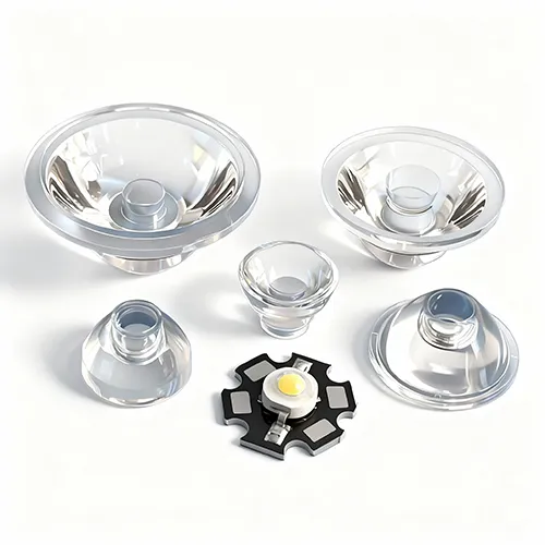
8. From DFM to Cleanroom Molding: How an LED Lens Program Runs
• DFM Review for Beam Performance. Part drawings undergo optical design engineering analysis to simulate TIR geometry, gate placement, and FWHM beam angles before tooling construction begins.
• Precision Mold Construction. Tooling cavities are built through precision mold manufacturing, with optical surface figure and roughness verified prior to production release.
• Cleanroom Molding. Injection molding is conducted in a controlled cleanroom environment to minimize particulate contamination, consistent with our optical lens injection molding process.
• Thermal-Grade Material Verification. Polymer selection is validated against the fixture’s maximum junction and operating temperatures rather than room-temperature specs, directly mitigating the failure modes detailed in Section 3.
9. Supplier Sourcing Checklist
Can you provide photothermal aging data (Yellowness Index over time) at our fixture’s actual operating temperature, rather than standard ambient specs?
Which optical polymers do you process — PC, PMMA, optical silicone (LSR), or COC/COP — and how do you evaluate thermal suitability for our profile?
Can you perform optical ray tracing to simulate and validate beam angle and FWHM prior to cutting tool steel?
How is gate placement controlled to eliminate flow lines and optical artifacts in the projected beam?
What cleanroom classification is maintained for optical injection molding?
Can your tooling design incorporate dimensional compensation for high-CTE materials like optical silicone?
Frequently Asked Questions
Why does my LED lens turn yellow over time?
Thermal yellowing is driven by photothermal degradation — a combined effect of operating heat and optical radiation — rather than UV exposure alone. Polycarbonate (PC) optics typically exhibit a gradual Yellowness Index increase before reaching a rapid failure threshold (Zone of Catastrophic Failure); PMMA remains stable up to its thermal limit (~80°C) and then degrades abruptly. The rate of degradation depends heavily on operating temperature and proximity to the LED junction.
What is a TIR lens and how is it different from a reflector?
A TIR (total internal reflection) lens uses refraction and total internal reflection within a solid molded optic to capture and redirect light, achieving optical efficiency above 90%. A standard reflector only redirects light that strikes its reflective walls, leaving direct center rays uncontrolled. A TIR lens manages the entire optical output for tighter beam control.
Should I use PC, PMMA, or silicone for my LED lens?
Selection depends on operating temperature near the optic and outdoor UV exposure. PMMA is commonly used for lower-temperature TIR optics requiring high clarity; PC provides higher impact strength for rugged fixtures operating under moderate thermal loads; optical silicone (LSR) is suited to high-power or close-proximity applications where sustained temperatures approach or exceed 100°C.
How do I choose an LED lens manufacturer for a new fixture program?
Select a manufacturer capable of providing photothermal aging data for your operational thermal profile, simulating optical performance before tooling, and optimizing gate location to prevent beam artifacts. Section 9 outlines key technical questions to evaluate before committing capital.
What production volumes are typical for custom LED lens tooling?
Prototype and photometric sampling runs typically range from a few hundred units for optical characterization before releasing production tooling. Unit costs decrease substantially at volume production scales.
An LED lens may appear to be a simple clear cover, but it functions as a precision optical element operating under continuous thermal and optical loads. Selecting materials based on your fixture’s actual thermal envelope—rather than ambient room-temperature specifications—helps determine whether an optic maintains photometric performance over its intended service life or degrades prematurely. Evaluating the criteria in Section 9 prior to tooling commitment helps ensure long-term product reliability.
Sourcing a Custom LED Lens or TIR Optic?
Talk to our optical engineering team about TIR lens design, thermal-grade material selection, and beam angle validation for your lighting program.
ATRMOLD — Precision Optical Lens Injection Molding & Mold Manufacturing