
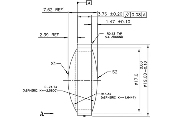
Most ISO 10110 guides are written for optical designers. This one is written for procurement engineers, product managers, and sourcing teams who need to send a complete, unambiguous lens specification to a manufacturer—and receive back exactly what was ordered.
By: ATRMOLD Engineering Team
July 2026
Reading time: 14 min
Category: Procurement Guide
- What is ISO 10110 and why is it used for optical lens drawings?
- Why Procurement Teams Need to Understand ISO 10110
- The Structure of ISO 10110: 13 Parts, 6 That Matter for Plastic Optical Lenses
- Notation Decode Guide: Reading the Numbers on Your Optical Lens Drawing
- What does scratch-dig mean on an optical drawing, and how does it relate to ISO 10110?
- Specification Disputes ISO 10110 Prevents—and Ones Ambiguous Drawings Cause
- RFQ Drawing Checklist: What to Send Before Requesting a Quote
- What if I do not have an ISO 10110 drawing yet—can I still get a quote for a custom optical lens?
- Industries That Require ISO 10110-Compliant Drawings
- First Article Inspection: How ISO 10110 Specs Are Verified Before Mass Production
- Working with ATRMOLD: What We Need From You Before Tooling Begins
People Also Ask
What is ISO 10110 and why is it used for optical lens drawings?
ISO 10110, titled “Optics and Photonics—Preparation of Drawings for Optical Elements and Systems,” is the international standard that defines how optical component specifications are communicated between optical designers, procurement teams, and manufacturers. It provides a standardized notation system—a set of numbered codes and symbols—that expresses optical tolerances, surface quality requirements, material specifications, and coating requirements in an unambiguous format universally understood across manufacturers globally.
It is used because optical lenses have properties that standard mechanical engineering drawing standards (ISO GPS, ASME Y14.5) cannot adequately express. Standard mechanical drawings handle dimensions, fits, and surface roughness in micrometers. Optical lens drawings require specification of surface form error in fractions of a wavelength of light, birefringence in nm/cm, scratch-dig ratios, and coating transmission bands—parameters that have no equivalent in conventional mechanical drawing notation.
ISO 10110 is the primary international standard for optical drawings. The American equivalent is ASME Y14.18M, but ISO 10110 is more widely used globally, including by optical manufacturers in Europe, Asia, and North America.
1. Why Procurement Teams Need to Understand ISO 10110
The most common cause of first-article rejection and tooling rework in custom optical lens projects is not manufacturing error—it is specification ambiguity. When a lens drawing does not clearly express what is required, the manufacturer interprets the gaps. Their interpretation and the customer’s expectation frequently do not match. The resulting dispute—over whether a surface finish is within specification, whether a transmittance measurement method is correct, or whether a coating is applied to the correct surface—causes weeks of delay and unnecessary rework costs.
ISO 10110 exists specifically to prevent this. A complete, correctly notated ISO 10110 drawing leaves no room for interpretation on the parameters that govern optical performance. When you send an ISO 10110-compliant drawing to a qualified optical lens manufacturer, both parties are reading the exact same specification language. Disputes decrease because the specification is technically precise.
For procurement teams, the practical value of understanding ISO 10110 includes:
- Evaluating supplier capability: A supplier who cannot read and respond to an ISO 10110 drawing is not an optical lens manufacturer—they are a general injection molder. ISO 10110 literacy is a minimum qualification for precision optical lens sourcing.
- Writing RFQs that generate comparable quotes: When every supplier quotes against the same unambiguous specification, the quotes are directly comparable. When suppliers quote against a vague description, each quote reflects different assumptions.
- Protecting IP: A complete drawing shared under NDA is your documented specification record. If the manufactured part deviates from the drawing, the drawing serves as the legal reference point for the dispute.
- Accelerating first-article approval: Manufacturers who receive a clear ISO 10110 drawing can build a complete first-article inspection plan before the mold is cut—not after first articles arrive and questions arise about which parameters to measure.
ISO 10110:2026 Update—Surface Form Tolerances:
ISO 10110-5 was updated in 2026 to change the preferred unit for surface form deviations from fringe spacings to nanometers. The fringe spacing notation is still permitted but must now explicitly include the base wavelength. If your existing drawings use fringe spacing notation (e.g., “3/0.5” for surface form), confirm with your manufacturer that they apply the correct wavelength reference (typically 632.8nm for HeNe laser interferometry) when interpreting the specification.
2. The Structure of ISO 10110: 13 Parts, 6 That Matter for Plastic Optical Lenses
ISO 10110 is a multi-part standard covering all aspects of optical element specification. For injection-molded plastic optical lenses, six parts are directly relevant to the drawings you send to your manufacturer:
| Part | Title | What It Covers | Priority |
|---|---|---|---|
| Part 1 | General | Drawing layout, general notation rules, tabular format for specifications | Essential |
| Part 2 | Material Imperfections — Stress Birefringence | Maximum birefringence specification in nm/cm — critical for polarization-sensitive and imaging applications | Essential |
| Part 3 | Material Imperfections — Bubbles and Inclusions | Maximum allowable bubbles and inclusions in the lens material — specified by grade number | Recommended |
| Part 5 | Surface Form Tolerances | Surface figure (flatness/sphericity deviation in waves or nm) and irregularity specification | Essential |
| Part 7 | Surface Imperfection Tolerances | Scratch-dig specification (surface defect limits) — the “cleanliness” of the optical surface | Essential |
| Part 8 | Surface Texture | Surface roughness specification in Ra (Angstroms or nm) — affects scatter and coating adhesion | Recommended |
| Part 9 | Surface Treatment and Coatings | Coating specification — type (AR, HC, hydrophobic), wavelength range, transmission requirement | Recommended if coated |
| Part 12 | Aspheric Surfaces | Aspheric surface profile specification — polynomial coefficients and form tolerance | Aspheric lenses only |
3. Notation Decode Guide: Reading the Numbers on Your Optical Lens Drawing
ISO 10110 uses a slash-notation system where each parameter is identified by a part number prefix followed by values. Here are the six notations you will see most frequently on plastic optical lens drawings:
0/
Part 2—Stress Birefringence
ISO 10110-2—Maximum allowable birefringence in the lens material
The notation 0/X specifies the maximum allowable stress birefringence in the lens, expressed in nm/cm of optical path. A lower number means the lens must have less internal stress—which is harder to achieve in injection molding and typically requires COP/COC material, elevated mold temperatures, and controlled injection speeds.
For most industrial sensor lenses and LED optics, birefringence is omitted. For imaging lenses, endoscope optics, and polarimetric sensor windows, this is a critical specification on the drawing—and one of the most commonly omitted, leading to failures during polarimetric testing at the customer’s facility.
0/10
Maximum birefringence 10nm/cm. Achievable with PMMA or COP/COC and an optimized process. Standard for machine vision and diagnostic imaging lenses.
0/2
Maximum birefringence 2nm/cm. Requires COP/COC material and a tightly controlled process window. Standard for semiconductor inspection and hyperspectral imaging optics.
1/
Part 3—Bubbles and Inclusions
ISO 10110-3—Material cleanliness: maximum allowable internal voids and particles
The notation 1/NxA specifies the maximum number (N) and size (A, in mm²) of bubbles and inclusions allowed within the lens aperture. This is controlled by resin quality (using certified optical-grade material with ISO lot certification) and proper desiccant drying before injection—moisture in the resin produces micro-voids during molding that cannot be corrected downstream.
For optical-grade PMMA and COP/COC, the material grade itself typically meets common bubble and inclusion specifications. This notation is most critical when specifying ultra-low inclusion grades for laser optics or high-resolution imaging components.
1/3×0.1
Maximum 3 bubbles or inclusions, each no larger than 0.1mm². Standard for precision imaging and sensor lenses.
3/
Part 5—Surface Form Tolerance
ISO 10110-5—How closely the lens surface matches its specified shape (sphere, asphere, flat)
The notation 3/A(B) specifies: A = maximum total surface form deviation (previously in fringes, now preferred in nm per the 2026 update); B = maximum irregularity (local deviation from the best-fit surface). Both affect optical performance—total form error shifts the focal length, while irregularity introduces wavefront error and scatter.
This is the most technically demanding tolerance to achieve in optical injection molding. Surface form depends on cavity accuracy, shrinkage compensation, and process control—parameters that must be addressed during DFM before cutting steel.
3/1(0.5)
Surface form deviation ≤1 fringe (≈316nm at 632.8nm), irregularity ≤0.5 fringe (≈158nm). Grade for high-resolution imaging lenses.
3/63(32)
Surface form deviation ≤63nm, irregularity ≤32nm (ISO 10110-5:2026 nm notation). Grade for high-resolution imaging lenses.
5/
Part 7—Surface Imperfection (Scratch-Dig)
ISO 10110-7—Maximum allowable surface defects: scratches and digs (pits)
The notation 5/N×A specifies maximum allowable surface defects: N is the maximum number of defects, and A is the maximum total area of all defects in mm². This corresponds conceptually to the American MIL-PRF-13830 scratch-dig notation (e.g., 60-40, 40-20) that many procurement engineers utilize—though the two systems are not mathematically identical.
For injection-molded optical lenses, surface defect limits are controlled by cavity surface quality (SPI A1 finish Ra ≤5nm) and a cleanroom molding environment. A lens produced in an ISO Class 7 cleanroom from an SPI A1 cavity will typically achieve a 60/40 equivalent surface quality. A 40/20 specification requires ISO Class 6 production and stringent cavity polishing.
5/5×0.25
Maximum 5 defects, total area ≤0.25mm². Approximately equivalent to 60/40 S/D—standard for machine vision, sensor, and industrial optical lenses.
5/1×0.06
Approximately equivalent to 40/20 S/D—required for medical diagnostic, laser, and semiconductor inspection optics.
P/
Part 8—Surface Texture (Roughness)
ISO 10110-8—Surface roughness Ra specification for the optical surface
Surface roughness is expressed as Ra in nanometers or Angstroms on the drawing. For injection-molded optical lenses, the cavity surface roughness directly replicates onto the lens optical surface—the mold must be polished to SPI A1 (Ra ≤5nm) to produce lenses meeting commercial-grade surface roughness specifications. Optical lens molds require significantly more polishing investment than standard injection molds.
Ra ≤ 5nm
SPI A1 equivalent. Standard for precision optical lenses—requires a mirror-polished mold cavity and an ISO Class 7 production environment minimum.
9/
Part 9—Surface Treatment and Coatings
ISO 10110-9—Coating type, wavelength range, and transmission/reflectance requirement
Coating specifications on ISO 10110 drawings reference ISO 9211 for coating nomenclature. The drawing indicates which surface receives which coating, the operational wavelength range, and the required optical performance (minimum transmission or maximum reflectance). For plastic optical lenses, common notations specify broadband anti-reflective (AR) coatings on one or both surfaces with reflectance below a specified percentage across the visible or NIR bands.
T>0.99 / 420-680nm
Transmittance greater than 99% across the 420–680nm visible band. Requires broadband AR coating on both surfaces. Standard for LED and imaging optics requiring maximum light throughput.
R<0.005 / 400-700nm
Reflectance less than 0.5% across 400–700nm. Premium broadband AR—appropriate for multi-element systems where inter-element reflection loss must be minimized.

People Also Ask
What does scratch-dig mean on an optical drawing, and how does it relate to ISO 10110?
Scratch-dig is a surface quality notation from American standard MIL-PRF-13830B that specifies allowable scratches and digs (pits or craters) on an optical surface. A scratch-dig designation of “60-40” means the maximum allowable scratch brightness matches a 60-unit scratch standard, and the maximum dig diameter is 0.40mm. Lower numbers indicate a cleaner surface requirement—40-20 is tighter than 60-40.
ISO 10110 Part 7 specifies the same surface quality requirement using a different notation system — 5/NxA where N is the number of defects and A is their total area in mm². The two systems are roughly comparable but not directly mathematically equivalent. For procurement purposes: 80/50 S/D corresponds approximately to 5/5×0.40; 60/40 S/D corresponds approximately to 5/5×0.25; 40/20 S/D corresponds approximately to 5/1×0.06. When specifying, choose one notation system and use it consistently — do not mix MIL S/D and ISO 10110-7 notation on the same drawing without confirming with the manufacturer which system takes precedence for inspection.
4. Specification Disputes ISO 10110 Prevents—and Ones Ambiguous Drawings Cause
❌ Dispute Scenario 1: Surface Quality Disagreement
- Ambiguous drawing states: “Surface finish: optical quality.”
- Customer expects: 60/40 scratch-dig equivalent, no visible defects under 10× magnification.
- Manufacturer delivers: Parts that pass internal visual inspection under ambient room light at a 45° angle.
- Result: Customer rejects the batch. Manufacturer insists the parts meet “optical quality.” Without an objective specification, resolving the dispute requires costly negotiations, re-runs, or project delays.
✅ How ISO 10110 Resolves This
The Part 7 notation states 5/5×0.25. Inspection methodology is defined, and defect count and total area in mm² are measurable using calibrated optical comparators. The drawing specifies the clear aperture zone where defect limits apply, ensuring edge chips outside the optically active area do not reject the part. First-article inspection yields documented surface quality metrics that both parties verify prior to mass production.
❌ Dispute Scenario 2: Coating Surface Ambiguity
- Ambiguous drawing states: “AR coating required.”
- Customer expects: Broadband AR coating on both surfaces, R<0.5% across 420–700nm.
- Manufacturer delivers: Single-surface AR coating on the convex side, optimized for 550nm, following standard single-surface coating practices when unspecified.
- Result: System transmittance measures 2% lower than required. The coating technically satisfies “AR coating” as written. A dispute arises over order fulfillment accuracy.
❌ Dispute Scenario 3: Transmittance Measurement Method
- Ambiguous drawing states: “Transmittance ≥ 90%.”
- Customer measures with: An integrating sphere at normal incidence, single wavelength (550nm).
- Manufacturer measures with: A photodetector at the lens center using a broadband white light source.
- Result: The same lens produces divergent test results. No measurement protocol was specified on the drawing, preventing resolution without establishing a shared testing procedure post-fabrication.
The Most Commonly Missing Specifications in Optical Lens RFQs:
Based on ATRMOLD’s engineering reviews of customer drawings: (1) Birefringence specifications missing on drawings for imaging and sensor lenses—discovered during customer system integration rather than incoming inspection; (2) Coating surfaces unspecified—customers assume dual-surface coating while manufacturers quote single-surface; (3) Clear aperture zone undefined—specifications are assumed to apply to 100% of the lens area by the customer, but not within the manufacturer’s inspection protocol; (4) Transmittance measurement methods unspecified—different metrology equipment yields inconsistent values on the same physical part.
5. RFQ Drawing Checklist: What to Send Before Requesting a Quote
Before submitting a request for quotation to an optical lens manufacturer, confirm that your drawing package includes the following parameters. Missing data will delay quotes or lead to inconsistent supplier assumptions.
📐 Dimensional Specifications
- Center thickness with tolerance (±mm)
- Outer diameter with tolerance (±mm)
- Radius of curvature—both surfaces (mm, with % tolerance)
- Wedge / TIR maximum (mm)
- Clear aperture zone defined (mm diameter)
- Aspheric coefficients if applicable (Part 12)
🔬 Optical Specifications
- Surface form tolerance—Part 5 notation (3/A(B))
- Surface imperfection—Part 7 notation (5/N×A)
- Birefringence max—Part 2 notation (0/X nm/cm)
- Surface roughness (nm or Å)
- Bubbles and inclusions grade—Part 3 (1/N×A)
- Transmittance or reflectance requirement with target wavelength range
🧪 Material Specifications
- Material specified (PMMA / PC / COP / COC)
- Refractive index requirement (if a specific grade is required)
- UV stability requirement (UV-stabilized grade)
- Biocompatibility requirement (ISO 10993 for medical applications)
- Operating temperature range
🎨 Coating Specifications
- Coating type specified (AR / HC / hydrophobic / anti-fog)
- Surface designation for coating (Surface 1, Surface 2, or both)
- Wavelength range for AR specification (nm)
- Transmission or reflectance target (T>X% or R<X%)
- Adhesion test method (cross-hatch per ISO 2409)
People Also Ask
What if I do not have an ISO 10110 drawing yet—can I still get a quote for a custom optical lens?
Yes—you can receive a preliminary budget quote without a finalized ISO 10110 drawing. Preliminary quotes will include explicit engineering assumptions that are refined once the final drawing is released.
The minimum information required for a meaningful preliminary quote includes:
- Lens geometry (approximate diameter, thickness, and radius of curvature or focal length)
- Material selection
- Coating requirements
- Estimated annual production volume
- Primary application (which dictates required tolerance grades)
If you do not have internal optical design resources, ATRMOLD’s optical design and engineering team can generate ISO 10110-compliant drawings based on your system-level requirements. We review your light source, detector specifications, working distance, and optical performance targets to produce a complete manufacturing drawing. This engineering review is integrated into the project workflow when ATRMOLD serves as the manufacturing partner.
While starting preliminary discussions without a drawing is standard practice, finalizing a tooling release requires a fully approved drawing. All tooling purchase orders at ATRMOLD require an approved ISO 10110 drawing prior to steel cutting to protect both parties from specification disputes.
6. Industries That Require ISO 10110-Compliant Drawings
While ISO 10110 represents best practice for all precision optical lens procurement, specific industries mandate compliance via regulatory standards, quality systems, or strict performance tolerances:
🏥 Medical Devices
FDA 510(k) and CE Mark submissions for optical medical devices require complete design controls and documentation. ISO 10110 drawings are the standard format referenced in Design History Files (DHF) under ISO 13485. Birefringence (Part 2) and surface quality (Part 7) specifications are mandatory for endoscope and diagnostic imaging optics.
🚗 Automotive ADAS
Tier-1 automotive suppliers sourcing camera and sensor lenses under IATF 16949 require complete engineering drawings prior to PPAP submission. ISO 10110 drawings serve as the accepted optical format in automotive design records. Surface form and transmittance are designated CTQ parameters requiring Cpk evidence.
📡 Industrial Sensors
Photoelectric, proximity, and LIDAR sensor manufacturers specifying lenses for multi-cavity production utilize ISO 10110 drawings to verify cavity-to-cavity consistency. Surface imperfection limits and transmittance uniformity represent critical specifications.
🔬 Semiconductor Equipment
Wafer inspection and metrology systems require ultra-tight birefringence specifications in plastic optics (0/2 or lower). ISO 10110 provides the necessary notation framework to define these polarimetric performance requirements.
🌾 Precision Agriculture
Hyperspectral imaging systems for drone-based crop monitoring require calibrated spectral responses. Transmittance uniformity across cavities and target wavelength bands must be fully documented using ISO 10110 Part 9 coating notations.
🛡️ Defense & Aerospace
Night vision, rangefinder, and targeting optics frequently reference both ISO 10110 and MIL-PRF-13830 standards. Procurement teams should establish with the manufacturer which standard governs quality inspection when both appear on project documentation.
7. First Article Inspection: How ISO 10110 Specs Are Verified Before Mass Production
A First Article Inspection (FAI) report for an ISO 10110-specified optical lens documents measurement data for every parameter defined on the drawing using calibrated optical metrology equipment. Passing FAI verifies that the mold geometry, surface finish, and processing parameters meet all optical criteria prior to mass production release.
What Equipment Is Used for Each ISO 10110 Parameter
- Center thickness, outer diameter (Part 1): Zeiss CMM or calibrated contact/non-contact gauge. Measurement uncertainty typically ±0.001mm.
- Surface form tolerance (Part 5): Zygo or Fizeau interferometer. Maps surface form deviation across the clear aperture. Report includes peak-to-valley (PV) and RMS values.
- Surface imperfection (Part 7): Calibrated visual inspection under dark-field or bright-field illumination, using reference standard comparators. Defect area measured with calibrated reticle or image analysis.
- Birefringence (Part 2): Polarimetric retardation measurement. Quantitative measurement in nm/cm across the clear aperture. Instruments include Hinds Instruments Exicor or equivalent Mueller matrix polarimeter.
- Transmittance (Part 9): UV-Vis spectrophotometer at specified wavelength range and incidence angle. Report includes spectral transmittance curve across the specified band.
- Surface roughness (Part 8): White light interferometer (Zygo NewView or equivalent) or AFM for sub-nm roughness measurement.
8. Working with ATRMOLD: What We Need From You Before Tooling Begins
To provide a complete quote and proceed to tooling without revision delays, submit the following specification package to ATRMOLD:
- ISO 10110-Compliant Drawing (PDF or DXF format): Covering geometry, surface form tolerance (Part 5), surface imperfection limits (Part 7), and material specifications, along with any application-specific parameters.
- Annual Production Volume: Used to determine mold cavity configuration, runner design, and unit cost targets.
- Application Description: Detailed operational parameters, including light source, operating wavelength band, working distance, and primary CTQ metrics (e.g., transmittance, focal length accuracy, birefringence limits).
- Required Quality Certifications: ISO 13485 for medical devices, IATF 16949 for automotive systems, RoHS compliance, or ISO 9001 baselines.
- First-Article Documentation Requirements: Identification of parameters requiring CMM reports, interferometric surface maps, spectrophotometric transmittance curves, or polarimetric retardation data.
If your drawing is incomplete or you require assistance selecting ISO 10110 parameters for your application, ATRMOLD’s optical design and engineering team provides complimentary pre-quote drawing reviews. We identify specification gaps, clarify clear aperture zones, and resolve potential manufacturing ambiguities. This drawing review represents the first step of our DFM process, eliminating specification disputes before tooling fabrication begins.
All projects include executed NDAs prior to file transfer, written mold ownership terms in purchase agreements, and complete Cpk validation data for critical dimensions prior to production sign-off. Manufacturing processes and quality documentation are strictly aligned with the ISO 10110 parameters defined on your engineering drawing.
Ready to Send Your Optical Lens Drawing for Review?
Submit your ISO 10110 drawing—complete or draft—for an engineering review of specification completeness prior to quoting. An NDA is executed before file review.
Related Articles & Pages