
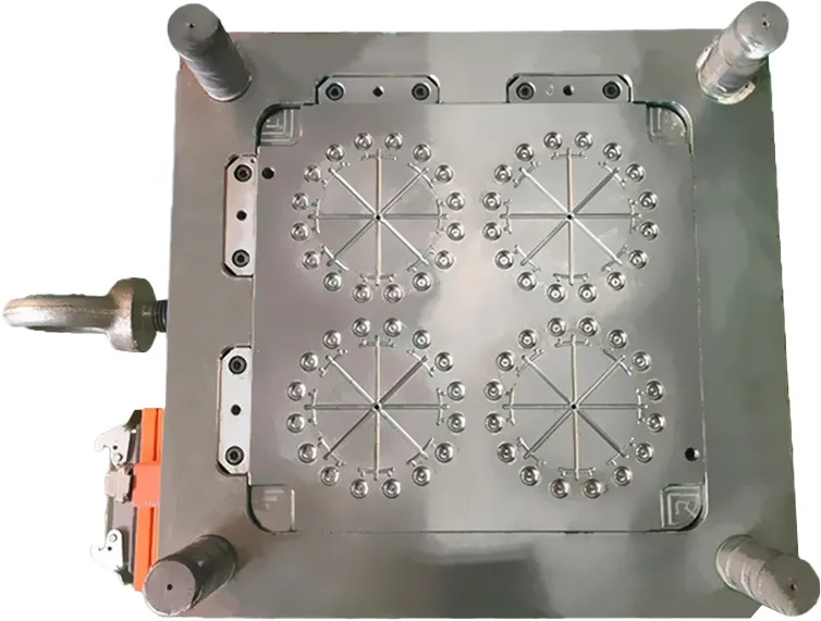
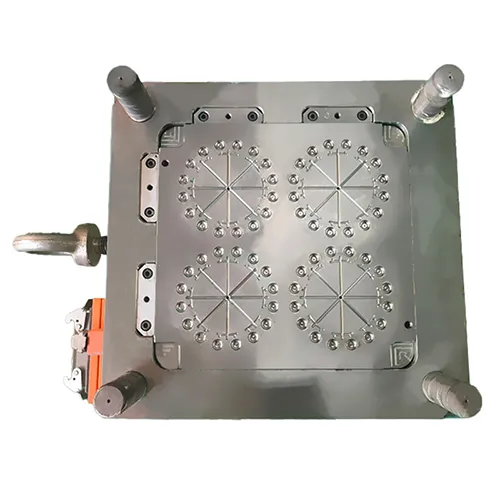
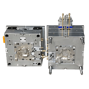
A multi-cavity optical lens mold that produces parts with varying transmittance, focal length, or birefringence across cavities is a production failure multiplied by the cavity count. True cavity-to-cavity consistency requires rigorous engineering design and validation from the first production run.
By: ATRMOLD Engineering Team
July 2026
Reading time: 15 min
Category: Mold Manufacturing
- Why Multi-Cavity Optical Lens Molds Are Harder Than Multi-Cavity Standard Molds
- The 4 Failure Modes That Cause Cavity-to-Cavity Variation in Optical Lens Molds
- Runner and Gate Balance: The Foundation of Cavity Consistency
- Cooling Channel Design: The Variable Most Often Under-Specified
- Selecting Cavity Count: Balancing Throughput and Consistency Risk
- Medical Lens vs. Industrial Sensor Lens: Different Consistency Requirements
- Mold Trial Validation: The Acceptance Tests That Confirm Cavity Consistency
- SPC in Production: Monitoring Cavity-to-Cavity Variation Over Time
People Also Ask
What is cavity-to-cavity consistency in optical lens injection molding?
Cavity-to-cavity consistency means that all cavities in a multi-cavity mold produce optical lenses with equivalent optical and dimensional properties—matching transmittance, focal length, birefringence levels, center thickness, and outer diameter—within the specified tolerance, across every shot throughout the production run.
For standard plastic parts, cavity-to-cavity variation is primarily a dimensional concern to ensure components fit the same assembly. For optical lenses, this variation affects both dimensional and optical performance: a lens from cavity 2 that transmits 89.5% versus a lens from cavity 1 that transmits 91.2% will alter the detection distance in a photoelectric sensor calibrated to cavity 1. This calibration error is invisible to standard incoming dimensional inspection and only surfaces after product deployment.
1. Why Multi-Cavity Optical Lens Molds Are Harder Than Multi-Cavity Standard Molds
Multi-cavity injection molds are standard practice across the plastics industry, running 4, 8, 16, or 32 cavities simultaneously to maximize throughput. For standard parts, the primary challenge is filling balance—ensuring each cavity fills at the same rate and receives identical packing pressure to maintain consistent dimensions and cosmetics.
For optical lenses, filling balance is necessary but insufficient. Two additional dimensions of consistency are required:
- Optical Performance Consistency: A part that fills correctly and meets dimensional tolerances can still exhibit varying transmittance, birefringence, or surface roughness if the cavity surface finish degrades unevenly, the gate geometry differs slightly between cavities, or thermal conditions vary across the mold. None of these variations are detectable through shot weight or fill time data.
- Long-Run Stability: A multi-cavity mold that shows consistency during first-article approval can develop cavity-to-cavity divergence over its production life due to uneven cavity wear, polish degradation, or runner erosion. For medical optical lens production under ISO 13485 or sensor lens production requiring stable calibration, this long-run drift poses a compliance risk.
The Calibration Consequence
Industrial sensor lenses and medical diagnostic optics are calibrated during final product assembly; the detection threshold, focal distance, or sensitivity is set based on the optical properties of the lens in that specific unit. If cavity-to-cavity variation in transmittance or focal length exceeds calibration tolerances, units assembled with lenses from different cavities will exhibit inconsistent field performance. For safety-critical medical devices or precision measurement instruments, this constitutes a product failure that cannot be corrected at the assembly stage.
2. The 4 Failure Modes That Cause Cavity-to-Cavity Variation in Optical Lens Molds
Failure Mode 1
Unbalanced Runner Fill
Geometrically balanced runners (such as H-patterns) do not guarantee hydraulically balanced filling. Shear heating in the runner system creates a temperature gradient across the melt cross-section, where the outer layers are cooler than the core. In branching runner systems, this thermal gradient causes uneven distribution to the cavities, making outer cavities fill differently than inner cavities despite equal runner lengths.
• Correction: Mold-flow simulation combined with short-shot trials to verify filling balance.
Failure Mode 2
Uneven Mold Temperature Distribution
Cavities experience different thermal conditions depending on their proximity to cooling channels, the mold’s thermal mass distribution, and heat transfer to the machine platens. Cavities closer to the mold edge cool faster than center cavities, producing disparate shrinkage profiles, variations in lens dimensions, and uneven residual stress.
• Correction: Conformal cooling integrated with mold temperature mapping during trials.
Failure Mode 3
Cavity Surface Polish Variation
In a multi-cavity mold, cavity inserts are polished individually. Even with an identical target surface roughness (Ra ≤ 0.02μm for an SPI A1 finish), subtle differences in manual or automated polishing techniques produce varying initial surface finishes. Over production cycles, cavities wear at different rates depending on gate-induced stress concentrations, resulting in surface quality divergence across cavities.
• Correction: White-light interferometric surface verification of all inserts before assembly.
Failure Mode 4
Gate Geometry Variation
Gate dimensions—width, depth, and land length—directly control the shear rate and the resulting flow-induced birefringence in the clear aperture of each lens. If gate dimensions vary between cavities due to electrical discharge machining (EDM) tolerances, cavities with larger gates produce lenses with lower birefringence, while smaller gates increase it. This variation remains undetected until polarimetric inspection is conducted on samples from each cavity.
• Correction: CMM verification of all gate dimensions prior to mold trials.
3. Runner and Gate Balance: The Foundation of Cavity Consistency
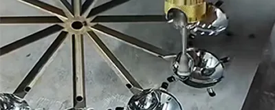
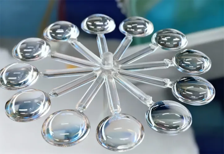
Runner design for multi-cavity optical lens molds utilizes geometric balance principles—equal flow path length and identical cross-sections from the sprue to every cavity gate. However, optical applications require runner designs that correct the rheological imbalance inherent in geometrically balanced systems.
The Melt Rotation Problem in Balanced Runners
In an H-pattern runner, the melt rotates as it passes through branching junctions. The outermost layer of the melt—which is the coolest and most highly sheared—is not uniformly distributed to the gate entry of each cavity. This asymmetric temperature and viscosity distribution generates filling and packing deltas between cavities, causing dimensional and optical variation despite perfect geometric runner symmetry.
The solution used in high-precision multi-cavity optical lens molds is active runner balancing — either through:
- Utilizing mold-flow simulation of the runner system prior to machining to identify cavities receiving higher shear-heated melt, then adjusting gate dimensions to equalize fill rates.
- Implementing sequential valve gating in hot runner systems to open gates on a controlled timing sequence, balancing fill rates independently of runner flow dynamics.
- Conducting short-shot validation trials during mold development to empirically verify that all cavities reach an identical fill fraction at the same injection time before mold acceptance.
Medical Optical Lens Requirement:
ISO 13485-compliant medical optical lens production requires documented evidence that the runner and gate system produces balanced filling across all cavities. Short-shot fill balance data and mold-flow simulation reports are standard documentation components within the Design History File (DHF) for medical device optical components. Gate dimension verification records are mandatory at initial qualification and at scheduled maintenance intervals.
4. Cooling Channel Design: The Variable Most Often Under-Specified
Uneven mold temperature distribution remains the most under-addressed failure mode in multi-cavity optical lens mold designs. Runner balance receives priority because fill imbalance is caught during short-shot trials. Cooling layout is frequently overlooked because the consequences of uneven thermal profiles—differential shrinkage, dimensional drift, and lens-to-lens focal length variation—develop gradually across a production shift and are easily misattributed.
Conventional vs. Conformal Cooling for Optical Lens Molds
Conventional straight-drilled cooling channels are restricted to straight lines between cavities and cannot achieve perfectly uniform cooling across the mold face. The outer corners of multi-cavity configurations—particularly in 4-cavity and 8-cavity layouts—are thermally isolated and run hotter than center cavities. Over a production shift, this thermal gradient builds, causing measurable divergence in part dimensions between corner and center cavity lenses.
Conformal cooling channels—which follow the three-dimensional contour of the cavity geometry rather than running in straight lines through the mold base—maintain temperature uniformity within ±2°C across all cavities. For optical lens production where dimensional tolerances are in the ±0.02–0.05mm range, this thermal uniformity translates directly into improved cavity-to-cavity dimensional consistency.
Industrial Sensor Lens Requirement:
Photoelectric and proximity sensor lenses molded in multi-cavity tools require strict cavity-to-cavity focal length consistency to ensure all units in a production batch maintain identical detection distances after assembly. A ±0.05mm center thickness variation between cavities produces a focal length shift that, for a 30mm working distance sensor, translates to an approximate ±1mm detection distance variation. While this may fall within standard tolerances for general sensors, it introduces significant errors in precision positioning sensors where required accuracy is <0.5mm.
5. Selecting Cavity Count: Balancing Throughput and Consistency Risk
Higher cavity count increases throughput but amplifies the difficulty of maintaining cavity-to-cavity consistency. For optical lens applications, cavity count selection should be driven by the consistency requirement, not solely by production volume targets.
| Cavity Count | Throughput Benefit | Consistency Challenge | Recommended For |
|---|---|---|---|
| 1–2 Cavities | Low — single or double production rate | Minimal — no inter-cavity variation by definition | Medical device lenses, R&D qualification, state-of-the-art tolerance applications Best for medical |
| 4 Cavities | 4× production rate vs. single | Moderate — manageable with mold-flow simulation and cooling design | Precision sensor lenses, diagnostic imaging optics, moderate-volume precision optical production Standard for sensor lens |
| 8 Cavities | 8× production rate | High — requires validated runner balance, conformal cooling, and per-cavity SPC monitoring | High-volume industrial and consumer optical lens production where optical tolerance allows process window flexibility Requires validation |
| 16+ Cavities | Maximum throughput | Very high — cavity-to-cavity validation requires extensive trial program; per-cavity traceability system recommended | Consumer LED optics, general-purpose sensor windows where transmittance tolerance >2% is acceptable Not for precision optical |
6. Medical Lens vs. Industrial Sensor Lens: Different Consistency Requirements
Medical Optical Lens Requirements
- ISO 13485 process documentation is mandatory for medical device compliance.
- Cavity counts are typically limited to 1–4 to minimize consistency risk.
- Per-cavity traceability: each lens is traceable to its specific cavity number, shot, and material lot.
- Birefringence specifications are critical for endoscope, OCT, and flow cytometry lenses.
- Biocompatible materials: COP or COC resins are preferred for low birefringence and bio-inertness.
- Sterilization compatibility: S136 stainless steel is mandatory for mold inserts to withstand autoclave environments.
- Cpk ≥1.67 is typically required on critical-to-quality dimensions.
- Zero-tolerance approach to lot release, allowing no statistical sampling exceptions.
Industrial Sensor Lens Requirements
- 4–8 cavity molds are standard to meet high-volume sensor production demands.
- Transmittance consistency must be within ±1–2% across cavities for calibration reliability.
- Focal length consistency is critical for fixed-distance detection applications.
- PMMA or PC resins are standard; birefringence tolerances are typically wider than medical optics.
- Automotive-grade process documentation is required for automotive sensor applications.
- Cpk ≥1.33 on critical dimensions is the baseline; ≥1.67 for safety-critical automotive systems.
- Intellectual property protection via NDA before drawing review is mandatory for proprietary sensor designs.
- Production volume is higher than medical runs, making cost-per-lens a primary constraint.
People Also Ask
Quality Standards for Medical Optical Lens Injection Molding
Medical optical lens injection molding is governed by ISO 13485, the international quality management standard for medical devices. This framework mandates documented design controls (including DFM reviews and design validation), production controls (including defined process windows and change control procedures), traceability (linking each production lot to specific material, equipment, and process records), and CAPA processes for non-conformances.
For the tooling, medical optical lens molds utilize S136 thru-hardened stainless steel cavity inserts to resist corrosion from sterilization agents (such as autoclave steam, EtO, and hydrogen peroxide vapor) encountered in cleanroom environments. Cavity-to-cavity consistency documentation—including runner balance metrics and per-cavity dimensional verification—is required as part of the Installation Qualification (IQ) and Operational Qualification (OQ) packages supporting FDA 510(k) or CE Mark submissions.
Biocompatibility of the lens material is governed by ISO 10993 for tissue and fluid contact. COP and COC resins are the most common optical polymers meeting ISO 10993 requirements, making them the standard material selection for implantable-adjacent or tissue-contacting medical optical components.
7. Mold Trial Validation: The Acceptance Tests That Confirm Cavity Consistency
Multi-cavity optical lens mold acceptance requires a validation program that evaluates cavity-to-cavity consistency rather than relying on overall part averages. Measuring 10 random parts from the entire mold and averaging the values masks cavity-to-cavity variation. Validation must track parts from each cavity independently.
1. Short-Shot Fill Balance Test:
Inject resin at reduced volumes (typically 70%, 80%, and 90% of full shot weight) and measure the fill fraction in each cavity. All cavities must reach an identical fill fraction simultaneously. If one cavity is systematically ahead or behind, runner or gate modification is required prior to full trials.
2. Per-Cavity Dimensional Measurement (25+ consecutive shots):
Inspect center thickness, outer diameter, and radius of curvature separately for each cavity across 25 or more consecutive shots. Calculate the mean and standard deviation per cavity. Cavity-to-cavity mean deltas must fall within the tolerance band, and the standard deviation within each cavity must confirm a Cpk ≥1.33 on critical dimensions.
3. Per-Cavity Transmittance Measurement:
Measure optical transmittance from each cavity independently using a UV-Vis spectrophotometer. Cavity-to-cavity transmittance variation must remain within acceptance specifications—typically ±1% for sensor lenses and ±0.5% for precision medical optics. Any cavity exhibiting systematically lower transmittance indicates a surface quality anomaly in that specific insert.
4. Per-Cavity Birefringence Check:
For birefringence-sensitive applications (such as medical diagnostics or sensors with polarimetric calibration), measure retardation from each cavity separately using crossed-polarizer inspection or quantitative polarimetry. Consistent birefringence across cavities verifies gate geometry uniformity; a single cavity with elevated retardation indicates a gate dimension or placement defect specific to that cavity.
5. Mold Temperature Mapping:
Measure mold surface temperature at each cavity location during steady-state production using a calibrated contact thermometer or thermal imaging camera. Temperature variations exceeding ±3°C between cavities indicate a cooling system imbalance that will drive dimensional drift. Resolve this thermal variance prior to production sign-off.
8. SPC in Production: Monitoring Cavity-to-Cavity Variation Over Time
A multi-cavity optical lens mold validated at first-article approval can develop cavity-to-cavity divergence during extended production. This occurs as individual cavities wear unevenly, cooling channels develop mineral scale, or gate edges erode based on their position in the flow field.
Production monitoring for multi-cavity optical lens molds must track dimensions per cavity rather than as an overall population. An SPC chart that averages measurements from all cavities will miss a single cavity drifting out of specification because the drifting cavity’s metrics are diluted by the conforming data of the remaining cavities. Per-cavity control charts are necessary to detect individual cavity drift before it generates non-conforming parts.
Practical SPC Implementation for Optical Lens Production
• Cavity Identification: Each lens must be marked with its cavity number at ejection (typically via a small witness mark or pit on the lens flange, outside the clear aperture) so measurement data traces back to specific cavities.
• Sampling Frequency: For precision optical lens runs, measure at least one lens per cavity per hour on critical-to-quality dimensions; increase to one per cavity per 30 minutes for new molds or immediately following maintenance.
• Control Chart Format: Deploy individual-moving range (I-MR) charts per cavity for dimensional measurements, alongside separate charts for transmittance and surface quality audit samples.
• Alert Thresholds: A single cavity trending toward its control limit triggers an immediate engineering investigation before it crosses the out-of-specification threshold.
Per-Cavity Traceability for Medical Lens Production:
ISO 13485 medical optical lens production programs require per-cavity traceability—the ability to identify which cavity molded each lens in a shipped lot. This is achieved by maintaining cavity identification on the part through shipping via the flange witness mark or a separate lot code linked to cavity-specific production records. If a field complaint or adverse event occurs, per-cavity traceability allows rapid root-cause isolation without requiring a recall of the entire production lot.
People Also Ask
How to Detect Cavity-to-Cavity Inconsistency in Optical Lens Production?
Cavity-to-cavity inconsistency in optical lens production is detected through isolated per-cavity measurement during mold trials and continuous production monitoring. Taking separate measurements from each cavity is critical; averaging measurements from all cavities together masks individual cavity deviations.
During mold trials, short-shot tests isolate fill balance; per-cavity dimensional measurement via CMM or non-contact profilometry reveals dimensional deltas; per-cavity transmittance testing using a spectrophotometer detects surface finish or material deviations; and crossed-polarizer or quantitative polarimetric inspection isolates birefringence variation between cavities.
In production, per-cavity SPC using individual-moving range control charts on critical dimensions is the standard monitoring methodology. Lenses must carry cavity identification (such as a small mark on the flange outside the clear aperture) so measurement data can be assigned to specific cavities rather than treated as a single population. A single cavity trending away from the mean while others remain centered serves as the early warning sign of cavity-specific wear, cooling imbalance, or surface quality degradation, allowing intervention before a non-conformance occurs.
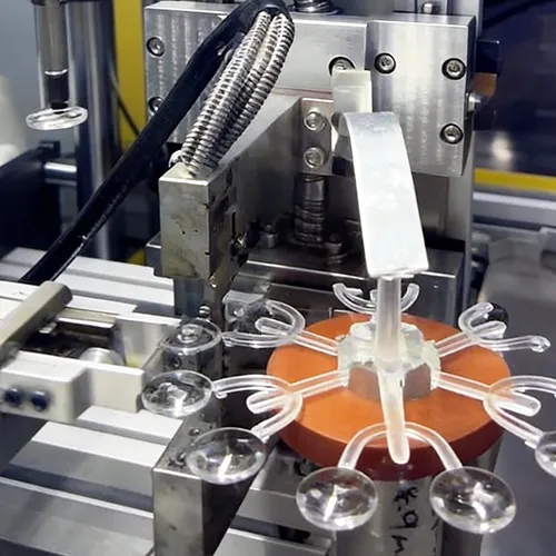
ATRMOLD’s multi-cavity optical lens mold design process incorporates mold-flow simulation for runner balance verification, per-cavity dimensional inspection at mold trials, and per-cavity transmittance measurement before final mold approval. For medical optical lens and precision sensor lens programs, we maintain per-cavity production records and provide Cpk data by cavity as part of the production lot documentation package.
If you are specifying a multi-cavity optical lens mold for a medical device or industrial sensor application, our mold manufacturing team and optical design and engineering team can review your cavity count, tolerance, and documentation requirements before tooling begins.
Specifying a Multi-Cavity Optical Lens Mold for Medical or Sensor Production?
Provide your application details, cavity count targets, and tolerance requirements. Our engineering team will advise on runner balancing strategies, cooling designs, and the cavity consistency validation protocol before tooling begins.
Related Articles & Pages