
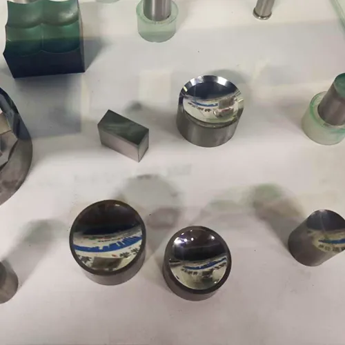
The gap between what your optical design calls for and what injection molding can consistently deliver in a 50,000-piece production run is where most tolerance specification errors occur. This guide explains what is achievable, why these limits exist, and how to close this gap before tooling fabrication begins.
By: ATRMOLD Engineering Team
July 2026
Reading time: 14 min
Category: Precision Manufacturing
1. What Are Optical Lens Tolerances and Why Do They Matter?
2. The Three Tolerance Grades: Commercial, Precision, and State-of-the-Art
3. Dimension-by-Dimension Tolerance Guide
4. How Cpk and SPC Turn Tolerances into Production Guarantees
5. What Actually Limits Tolerance in Volume Production
6. How Are Optical Lenses Made? Process Impact on Tolerance
7. Tolerance Requirements by Application and Industry
1. What Are Optical Lens Tolerances and Why Do They Matter?
People Also Ask
What is an optical tolerance?
An optical tolerance is the permissible deviation from a specified dimension, surface form, or optical property in a manufactured lens. Unlike mechanical tolerances — which govern mechanical fit, clearance, and structural integrity — optical tolerances control properties that directly affect wavefront propagation, light transmission, and reflection: radius of curvature, center thickness, surface figure (flatness or sphericity), surface roughness, wedge angle, and optical axis decenter.
In injection-molded plastic optical lenses, the primary dimensional tolerances are center thickness, outer diameter, and radius of curvature. The primary optical tolerances are surface figure (measured in waves, λ), surface irregularity, and surface scratch-dig quality (expressed as an S/D rating, such as 60/40 or 40/20). All of these parameters are specified in the engineering drawing and verified via optical metrology before production approval.
Tolerances define the acceptable range of variation around a nominal dimension. For a lens with a 20mm diameter specification, a ±0.05mm diameter tolerance dictates that every conforming part must measure between 19.95mm and 20.05mm. Parts outside this range fail inspection. However, a process that consistently yields parts within range but with high part-to-part variation approaching the limits is also problematic.
This distinction—between a tolerance band and the process capability required to consistently maintain that band in high-volume production—is where most optical tolerance specification issues originate. An optical engineer can easily specify ±0.02mm on a print. Whether a specific mold tool and injection molding process can consistently achieve ±0.02mm across a 50,000-part production run is a different matter. The answer depends on material selection, part geometry, mold architecture, and process control limits — not simply the drawing callout.
The Core Challenge:
A tolerance specification defines the acceptable limits of a dimension. A process capability index (Cpk) measures whether a production process can reliably manufacture within those limits across thousands of cycles under real-world factory conditions. Specifying tight tolerances without understanding the achievable Cpk in optical injection molding is the leading cause of costly tool rework after first article inspection (FAI).
2. The Three Tolerance Grades: Commercial, Precision, and State-of-the-Art
The plastic optics manufacturing industry classifies injection-molded optical lens tolerances into three distinct grades. These grades reflect what is technically achievable at different tiers of tooling precision, process control, and manufacturing cost. Identifying which grade your application truly requires prevents unnecessary manufacturing premiums.
| Tolerance Parameter | Commercial | Precision | State-of-the-Art |
|---|---|---|---|
| Radius of Curvature | ±5% | ±2% | ±0.5% |
| Effective Focal Length (EFL) | ±5% | ±2% | ±1.0% |
| Center Thickness | ±0.13mm | ±0.05mm | ±0.020mm |
| Outer Diameter | ±0.13mm | ±0.05mm | ±0.020mm |
| Surface Figure (waves) | 5λ (2.5 fringe) | 3λ (1.5 fringe) | 1λ (0.5 fringe) |
| Surface Irregularity | 2.5λ | 1.5λ | 0.5λ |
| Surface RMS Roughness | <100Å | <50Å | <20Å |
| Surface Scratch-Dig (S/D) | 80/50 | 60/40 | 40/20 |
| Wedge (TIR) | <0.025mm | <0.015mm | <0.010mm |
| Radial Displacement | <0.100mm | <0.050mm | <0.020mm |
| Part-to-Part Repeatability | <2% | <1% | <0.5% |
Important:
These tolerances apply to 10–25mm diameter lenses. This range covers the majority of precision injection-molded optical components. Larger lenses are more difficult to control due to increased volumetric shrinkage variation across a larger surface area. Conversely, smaller micro-optics require specialized tooling that can hold tighter linear dimensions but may require relaxed surface quality specifications.
Which Grade Does Your Application Need?
- Commercial Grade: Engineered for LED illumination optics, general-purpose sensor windows, protective lens covers, and consumer lighting diffusers. This grade uses cost-optimized tooling and standard molding process controls.
- Precision Grade: Engineered for machine vision lenses, industrial sensor heads, automotive ADAS optics, and medical diagnostic components. This grade requires premium mold steel, tight closed-loop process monitoring, and regular CMM verification.
- State-of-the-Art: Engineered for high-resolution imaging lens assemblies, interferometric sensor elements, precision spectrometers, and medical endoscope optics. This grade demands maximum tooling accuracy, all-electric injection molding machinery, and interferometric surface verification.
3. Dimension-by-Dimension Tolerance Guide
Each dimensional parameter on an optical lens behaves differently during the injection molding cycle, responds to distinct process variables, and exerts a unique impact on optical system performance.
Center Thickness
Center thickness establishes the optical path length through the lens element. Variation in center thickness directly shifts the effective focal length (EFL) and alters power distribution. For meniscus or plano-convex lenses, center thickness and surface curvature jointly define focal length, making center thickness variations a primary contributor to focal length errors.
In volume production, center thickness consistency depends heavily on shot weight uniformity and packing pressure stability. All-electric injection molding machines with closed-loop position control maintain center thickness more consistently than conventional hydraulic presses.
Commercial (LED / Illumination)
±0.13mm
Precision (Machine Vision / Sensor)
±0.05mm
State-of-the-Art (Imaging / Medical)
±0.020mm
Outer Diameter
Outer diameter tolerance determines whether the lens mounts securely and consistently inside its mechanical housing or lens barrel. A lens that is 0.1mm oversized will not seat correctly in a precision press-fit assembly, while an undersized lens can experience mechanical play, tilt, or allow stray light to bypass the aperture stop. In multi-lens assemblies, diameter variations cause compounding axial alignment errors between elements.
Outer diameter is governed primarily by the physical mold cavity dimensions and material shrinkage rates. Shrinkage for optical-grade PMMA varies between 0.2% and 0.8% depending on wall thickness variations and process settings, requiring precise cavity oversize compensation that must be validated during mold trials.
Commercial
±0.13mm
Precision
±0.05mm
State-of-the-Art
±0.020mm
Radius of Curvature
Radius of curvature is the primary geometric variable used to set optical power. A 2% radius error on a 50mm radius surface equates to a 1mm deviation, which shifts the focal length of a simple lens by several percentage points. In multi-element systems, radius errors stack up alongside other dimensional variations, potentially dropping the system below its modulation transfer function (MTF) specification even if each lens passes its standalone dimensional check.
The radius is established by the precision geometry of the mold insert and maintained by cavity polishing. Over an extended production life, tool wear and repeated maintenance polishing gradually alter the insert profile. Regular interferometric monitoring of the mold insert is necessary to catch and correct this drift before it impacts production yields.
Commercial
±5% of nominal radius
Precision
±2% of nominal radius
State-of-the-Art
±0.5% of nominal radius
Wedge (TIR — Total Indicated Runout)
Wedge represents the non-parallelism between the two optical surfaces of a lens, creating an unwanted prismatic effect that deflects the optical axis. In imaging assemblies, wedge introduces image tilt and coma; in single-element sensor optics, it shifts the exiting beam orientation away from nominal.
Wedge originates from mechanical misalignment between the stationary and moving mold inserts during tool assembly, or from asymmetric cooling that tilts one surface relative to the other during solidification. It is quantified as Total Indicated Runout (TIR), measuring the maximum parallel deviation of the rear surface reference relative to the front surface.
Commercial
<0.025mm TIR
Precision
<0.015mm TIR
State-of-the-Art
<0.010mm TIR
People Also Ask
What material is an optical lens made of?
Injection-molded plastic optical lenses are most commonly manufactured from three engineering thermoplastics: PMMA (Polymethyl Methacrylate), PC (Polycarbonate), and COP/COC (Cyclic Olefin Polymer / Cyclic Olefin Copolymer). Each features unique optical and mechanical properties.
PMMA provides high optical clarity (~92% visible light transmittance) and is standard for LED optics and light guides. PC provides superior impact resistance and serves as the baseline material for automotive and protective eyewear. COP/COC features near-zero moisture absorption and very low stress-induced birefringence, making it the preferred choice for medical diagnostic optics and precision sensing.
Material selection directly impacts achievable production tolerances. COP/COC’s negligible moisture absorption eliminates batch-to-batch dimensional drift caused by environmental humidity, whereas PMMA’s moisture sensitivity requires strict resin-drying protocols to prevent post-molding dimensional variation.
4. How Cpk and SPC Turn Tolerances into Production Guarantees
A drawing tolerance band states the acceptable dimensional limits. The Process Capability Index (Cpk) measures whether a manufacturing process can reliably produce components within those limits, tracking the margin between process variation and the tolerance boundaries.
Cpk is calculated as the distance from the process mean to the nearest tolerance limit, divided by three times the process standard deviation (sigma). A Cpk of 1.33 indicates that the nearest tolerance limit sits at least four standard deviations away from the process mean, yielding a theoretical defect rate of approximately 64 parts per million (PPM). This is the widely accepted industry minimum for automotive-grade critical-to-quality (CTQ) dimensions.
Cpk < 1.0
Not Capable
Process variation exceeds the tolerance band. Defective parts will occur regularly during production. This is unacceptable for volume manufacturing of precision optics.
Cpk ≥ 1.33
Capable
The widely accepted industry minimum for critical dimensions, yielding a ~64 PPM defect rate. This is acceptable for most automotive and industrial precision optical applications.
Cpk ≥ 1.67
Excellent
Yields a ~0.6 PPM defect rate. This is the target threshold for medical optics and high-reliability sensing systems where defective components present significant field risks
At ATRMOLD, we establish clear Cpk targets for every critical dimension during the mold trial phase. A tool is not released for mass production until first-article samples demonstrate the required Cpk across critical-to-quality (CTQ) dimensions. This ensures that a tool producing acceptable initial samples will not drift out of specification during full production runs.
SPC in Production
Statistical Process Control (SPC) translates initial process capability into a continuous quality assurance tool. Control charts monitor critical parameters across production shifts to identify trends. For example, a dimension drifting toward a control limit triggers a process engineering investigation and adjustment before non-conforming parts are molded. For optical lenses, SPC is continuously applied to center thickness, outer diameter, and shot weight (used as a process indicator for volumetric filling consistency). Industry data confirms that integrated quality monitoring via real-time SPC reduces defect response windows from an average of 50 minutes to under 5 minutes.
5. What Actually Limits Tolerance in Volume Production
The tolerances listed in our three-grade classification are highly achievable, but their implementation depends heavily on lens geometry, material selection, and tooling budgets. Several physical production variables limit tolerance thresholds regardless of mold machining precision.
Volumetric Shrinkage Variation
All optical thermoplastics shrink as they cool: PMMA shrinks by 0.2%–0.8%, PC by 0.5%–0.7%, and COP/COC exhibits a similar range. The mold cavity is machined oversized to compensate for this behavior. However, shrinkage rates are not uniform; they vary based on localized wall thickness, mold core temperatures, injection velocities, and packing pressures. Across an extended production run, shot-to-shot fluctuations in these parameters produce dimensional variation in the finished lens. Holding tighter tolerances requires exceptionally tight process windows, eventually hitting a threshold where baseline process variation requires 100% sorting.
Thermal Drift within the Tool
Mold temperature directly controls polymer shrinkage, surface micro-replication, and cooling rates. A tool that begins a production run at 80°C can drift to 82°C–85°C over several hours as shear energy and melt heat accumulate. This thermal drift alters part dimensions and can push a validated process out of its qualified Cpk window without triggering a standard machine alarm. Continuous, direct mold temperature monitoring — rather than relying solely on the water-temperature controller setpoint — is essential for high-precision optics.
Material Lot-to-Lot Variation
Optical-grade resins are certified to specific ranges for molecular weight, melt flow index, and moisture absorption. However, slight lot-to-lot variations within these certified bounds can shift finished component dimensions enough to impact tight Cpk targets. For state-of-the-art tolerance requirements, raw material lot qualification—running a sample batch through the validated process and verifying dimensions before release to full production—is standard practice.
People Also Ask
How accurate is injection molding for optical lenses?
The accuracy of an injection-molded lens depends directly on the tooling classification, process control limits, and material management executed on the shop floor. Commercial-grade production yields dimensional tolerances of ±0.13mm on diameter and center thickness. Precision-grade production regularly achieves ±0.05mm using premium tool steels and SPC tracking. State-of-the-art operations can hold ±0.020mm on center thickness and diameter, while maintaining surface roughness below 20Å.
Process capability (Cpk) is the correct technical metric for assessing production accuracy. A single first-article sample matching the drawing does not ensure a stable 50,000-part production run. A Cpk of ≥1.33, validated via statistical sampling during first-article testing, represents the industry baseline for high-volume optical components.
Compared to CNC-machined glass optics, glass grinding can achieve tighter surface form tolerances (such as 0.1λ surface figure vs. the 0.5λ–1λ typical for injection molding), but at a 10x to 50x increase in unit cost and cycle times that are incompatible with mass production. The choice between glass and plastic is fundamentally a cost-to-volume optimization decision.
6. How Are Optical Lenses Made? Process Impact on Tolerance
People Also Ask
How are optical lenses made by injection molding?
Injection-molded optical lenses are manufactured by plasticizing optical-grade resin (such as PMMA, PC, or COP/COC), injecting the molten polymer under high pressure into a temperature-controlled metal mold cavity, and allowing it to solidify prior to mechanical ejection. The mold cavity surface is machined to a mirror-grade finish (SPI A1, Ra ≤ 5 nm) to ensure accurate replication of surface topography onto the lens surface.
The production sequence requires:
- Thorough resin drying to eliminate moisture-induced defects.
- Controlled volumetric injection into the cavity at precise velocity profiles.
- A sustained packing phase to compensate for material shrinkage during cooling.
- Uniform cooling managed by internal mold thermal channels.
- Automated mechanical ejection and robot transfer to a cleanroom inspection station.
For precision optics, manufacturing is executed within an ISO Class 6 (Class 1,000) or ISO Class 7 (Class 10,000) cleanroom environment using all-electric injection molding machines. These presses provide the precise closed-loop position and pressure controls necessary to minimize the shot-to-shot variation that limits volume tolerances.
The production steps outlined above directly govern achievable tolerances. The packing phase — where additional melt is packed into the cavity to offset thermal contraction — also introduces residual mechanical stress and orientation-induced birefringence if over-packed. Achieving tight linear dimensions (which favors higher packing pressure) while minimizing birefringence (which favors lower packing pressure) requires mapping a precise process window for every lens geometry. This optimization is a primary goal of a structured mold trial.
Injection Compression Molding (ICM) for Enhanced Tolerance Control
Standard injection molding fills the cavity through a restrictive gate and packs material against solidifying walls. Injection Compression Molding (ICM) modifies this process by introducing a controlled tool compression stroke; the mold inserts close slightly further during the packing stage, applying uniform mechanical pressure across the entire lens surface rather than relying exclusively on gate pressure. Technical data indicates that ICM achieves superior surface replication, reduced part warpage, and lower residual stress for demanding components like Fresnel lenses or thin diffractive optics, though it requires more complex tooling and advanced press control configurations. ICM is typically specified for state-of-the-art applications where standard molding cannot meet surface figure or birefringence requirements.
7. Tolerance Requirements by Application and Industry
The appropriate tolerance specification is determined by the system’s optical requirements, not by the industry category. A medical device can utilize a loose-tolerance protective shield, while an agricultural sensor may require precision-grade dimensional controls to ensure consistent detection ranges. The optical design dictates the tolerance.
Commercial to Precision Grade: TIR lenses and secondary optics for architectural, automotive, and street lighting. Center thickness tolerance: ±0.05mm to ±0.13mm. Diameter: ±0.05mm to ±0.13mm. Focal length tolerance: ±2% to ±5%. Surface quality: 60/40 to 80/50 S/D. Highly cost-sensitive applications.
Precision Grade: Lenses used in proximity, photoelectric, and time-of-flight sensors. Center thickness: ±0.05mm. Diameter: ±0.05mm. Focal length: ±2%. Cavity-to-cavity uniformity in multi-cavity tooling is critical to maintain standardized sensing ranges across product populations.
Precision Grade: Optomechanical assemblies for automated inspection and traffic enforcement systems. Demanding MTF requirements mandate a minimum 60/40 scratch-dig surface quality. Center thickness: ±0.05mm. Birefringence must be tightly controlled but rarely requires a zero-stress spec.
Precision Grade: ADAS camera and LiDAR lenses requiring rigorous statistical process control with a Cpk ≥1.33 on all CTQ dimensions. Environmental operating windows ranging from −40°C to 120°C require high post-mold dimensional stability that commercial-grade tooling cannot deliver. Polycarbonate is the standard material choice.
Commercial to Precision Grade: Impact-resistant PC lenses meeting ANSI Z87.1 and EN166 standards. While impact performance is primary and optical tolerances are secondary, dimensional control over outer diameter and thickness is critical to ensure proper frame retention and automated assembly fit. Center thickness: ±0.05mm to ±0.10mm.
Medical Diagnostic Optics
Precision to State-of-the-Art: Endoscope lenses, clinical diagnostic imaging systems, and flow cytometry optics. Requires a continuous Cpk ≥1.67 on critical-to-quality dimensions. COP/COC resins are preferred for their low birefringence, chemical resistance, and biocompatibility. Full ISO 13485 production documentation is mandatory.
Diving & Watersports Optics
Commercial to Precision Grade: Tempered PC lenses for dive masks and marine instrumentation housings. Impact resistance is the primary driver, with mild optical distortion tolerated. Outer diameter tolerances for waterproof housing seals are frequently tighter than the optical surface specifications. Anti-fog coatings are standard.
Agricultural & Field Sensing
Commercial to Precision Grade: Sensor window optics for multi-spectral crop monitoring and soil analysis. Severe outdoor UV exposure and thermal cycling (−20°C to 70°C) require robust material stability. PC or UV-stabilized PMMA is standard, paired with a hard coat and hydrophobic topcoat to reduce field maintenance intervals.
8. The Overspecification Problem: Tighter ≠ Better
People Also Ask
What happens if optical tolerances are too tight for injection molding?
Specifying tolerances beyond what the injection molding process can reliably sustain in volume production introduces several engineering and financial penalties:
- Initial first-article parts may pass inspection, but production batches will drift out of spec as baseline parameters fluctuate, forcing 100% inspection-and-sort sorting instead of statistical sampling.
- The mold requires repeated modifications to establish a narrow process window, extending lead times and increasing engineering costs.
- Scrap rates rise significantly, driving up the effective unit cost.
- The drawing requirements may become physically unachievable without upgrading to complex alternative processes (like Injection Compression Molding or CNC glass grinding) at a substantially higher price point.
The correct tolerance specification should match the system’s optical budget precisely without adding unnecessary margin. Executing a tolerance stack-up analysis before finalizing the tool print highlights which individual dimensions actively drive optical performance, allowing non-critical parameters to be relaxed to lower production costs while maintaining final system performance.
Overspecification increases cost, drops production yields, and complicates manufacturing replication across production sites. Calling out a ±0.020mm center thickness on an LED illumination optic that performs identically at ±0.10mm does not yield a better product; it simply increases production overhead. Every fraction of a millimeter tightened past functional necessity represents an unnecessary cost.
This problem occurs most frequently in two scenarios: when an engineering print is adapted directly from a legacy glass optics program (where tight tolerances are standard practice and processing mechanics differ completely) without optimization for plastic injection molding, or when an engineer tightens all drawing tolerances simultaneously as a safety margin rather than conducting a dedicated sensitivity analysis.
Sensitivity Analysis Before Tightening
Prior to specifying any tolerance tighter than precision grade, model the optical performance delta per unit of geometric variation. If a 0.05mm center thickness variation shifts the effective focal length by a mere 0.1% — well within your system’s performance budget — there is no technical justification to specify ±0.02mm. Reserve tight specifications exclusively for the specific dimensions that actively drive system performance.
9. How to Specify Optical Lens Tolerances Correctly
An effective tolerance specification balances three independent factors: system optical sensitivity, process capability (Cpk), and cumulative tolerance stack-up. Following this structured sequence ensures a printable drawing that delivers the required field performance.
Step 1: Execute Tolerance Stack-Up Analysis First
Run a worst-case and Root-Sum-Square (RSS) tolerance stack-up analysis before finalizing individual dimensions. This defines which tolerances dominate system performance. Tighten only those critical nodes and relax the remaining dimensions. Skipping this step often results in engineers tightening non-critical features while leaving sensitive parameters too loose.
Step 2: Match Tolerance Grade to the Application
Use our three-grade classification table as your baseline reference. Start with commercial-grade limits, upgrading to precision limits only for parameters identified as optically sensitive by your stack-up model. Move to state-of-the-art parameters only when precision limits fail to satisfy the optical budget and the application supports the associated tooling premium.
Step 3: Validate Cpk Achievability Prior to Tooling
Confirm with your injection molder that the proposed drawing tolerances are manufacturable at a Cpk ≥1.33 (or ≥1.67 for medical device programs) within the target resin. This verification is the primary objective of a Design for Manufacturability (DFM) review, identifying unachievable tolerances before tool steel is cut.
Step 4: Explicitly Define CTQ Dimensions on the Print
Clearly mark Critical-to-Quality (CTQ) dimensions directly on the engineering drawing. These designated parameters dictate the collection of Cpk data during first-article inspection and govern the active SPC control charts during mass production. Non-CTQ dimensions can be monitored via standard sampling plans, reducing metrology overhead by focusing inspection resources on critical attributes.
Step 5: Adopt Standardized ISO 10110 Notation
Use ISO 10110 notation and formatting for all optical drawings. This standard provides an unambiguous, globally recognized framework for specifying surface figure, irregularity, roughness, and scratch-dig specifications. It ensures that your internal optical design team, quality engineers, and our production technicians interpret the inspection criteria identically, eliminating acceptance disputes during first-article approval.
If you are developing an optical lens project and need a tolerance review before drawing finalization, our optical design and engineering team offers a free feasibility review that specifically assesses whether your tolerances are achievable in volume production at the required Cpk — and which ones may need adjustment before tooling begins.
Need a Tolerance Feasibility Review Before Tooling?
Submit your current lens drawings and optical requirements to our engineering team. We will review your tolerance stack-up, verify manufacturability at a target Cpk ≥1.33 for volume production, and identify any geometric or dimensional risks before tool fabrication begins.
Related Articles & Pages