
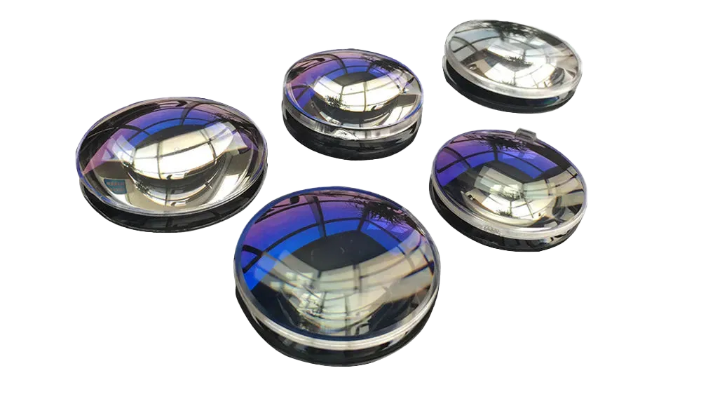
Most optical lens defect guides focus only on surface-level symptoms. This engineering guide analyzes why each defect forms, details its precise impact on optical performance, and explains how Zero-Defect Manufacturing (ZDM) is shifting quality control in 2026 from statistical sampling to 100% inline automated inspection.
By: ATRMOLD Engineering Team
July 2026
Reading time: 15 min
Category: Quality Control
1. Why Optical Lens Defects Are Different from Standard Plastic Defects
2. Defect 1: Silver Streaks (Moisture Splay)
3. Defect 2: Birefringence (Flow-Induced Optical Distortion)
4. Defect 3: Sink Marks and Surface Form Deviation
5. Defect 4: Optical Haze (Cloudiness)
6. Defect 5: Weld Lines in the Optical Zone
7. Defect 6: Warpage and Dimensional Instability
8. Defect 7: Burn Marks and Thermal Degradation
9. 2026: AI-Assisted Inline Inspection and Zero-Defect Manufacturing
1. Why Optical Lens Defects Are Different from Standard Plastic Defects
In standard commercial plastic injection molding, a defect is primarily a cosmetic or structural problem. A sink mark on a housing panel is an aesthetic blemish; a weld line on an enclosure reduces structural impact strength; parting line flash adds a manual deburring step. While these are manufacturing non-conformances, they rarely prevent the component from performing its core function.
For optical lenses, every defect category carries a functional performance penalty that directly impairs light transmission:
- Silver streaks scatter incident light, reducing total transmittance and inducing visible artifacts in imaging paths.
- Birefringence alters the polarization state of transmitted light, disrupting polarization-dependent sensing arrays and degrading wavefront quality.
- Sink marks deform the optical surface profile away from its designed radius, shifting focal length and introducing severe optical aberrations.
- Haze scatters micro-rays, reducing contrast in imaging applications and lowering the signal-to-noise ratio (SNR) in sensing arrays.
- Weld lines in the clear aperture create localized refractive index discontinuities that scatter and refract wavefronts unpredictably.
Consequently, a minor cosmetic flaw in general molding represents a total functional failure in optical molding. A lens that passes a standard visual inspection may still fail modulation transfer function (MTF) or wavefront error testing. These failures are often detected only after the lens has been integrated into a complex optical assembly, multiplying the cost of scrap.
The Precision Inspection Gap
Standard injection molding quality control relies on Acceptable Quality Level (AQL) statistical sampling. For precision optical components, a defect rate that passes (AQL) thresholds can still allow non-conforming lenses to reach the assembly line. This is driving the 2026 industry transition toward 100% inline optical inspection.
2. Defect 1: Silver Streaks (Moisture Splay)

Silver Streaks / Moisture Splay
Critical
Silver streaks (also termed splay marks) manifest as silvery, linear streaks radiating from the gate entry point or distributed across the lens face. Under cross-polarized or darkfield backlighting, they appear as elongated micro-voids aligned with the melt flow direction.
Optical Performance Impact: Each silver streak represents a pocket of trapped gas or vaporized moisture at or near the lens surface. These micro-voids act as refractive interfaces, scattering incident light out of the intended optical path. In imaging lenses, splay drastically reduces contrast and induces stray light artifacts. In sensor optics, it attenuates signal intensity. Any silver streak intersecting the clear aperture is cause for immediate part rejection.
Root Cause
- Resin moisture above spec (most common): steam vaporizes in barrel, injects with melt
- Excessive barrel temperature or residence time causes polymer degradation and gas release
- Contaminated resin or hopper
- Shear-induced degradation from excessive injection speed through undersized gate
Prevention Strategies
- PMMA: dry to <0.04% at 80°C / 4–6h before every lot
- PC: dry to <0.02% at 120°C / 4–6h — non-negotiable
- COP/COC: minimal drying needed (<0.01% absorption)
- Check moisture before production, not just on delivery
- Minimize barrel residence time by matching barrel size to shot volume
Detection Methodologies
- Backlighting + visual inspection (experienced operator)
- AI vision system: trains on backlit image dataset, flags streak patterns with >99% accuracy
- Haze meter (quantitative transmittance measurement)
- Inline cavity pressure monitoring: pressure signature changes when gas is present
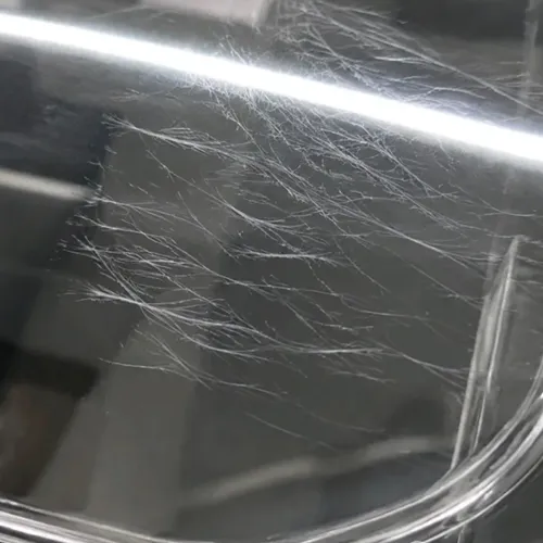
Silver Streaks and Splay Marks on Transparent Injection Molded Parts
3. Defect 2: Birefringence (Flow-Induced Optical Distortion)

Birefringence — Flow-Induced Internal Stress
Critical for Precision Optics
Birefringence is invisible to the naked eye under standard ambient lighting. When viewed under cross-polarized light or a polariscope, it manifests as multicolored fringe patterns or stress rings that indicate optical anisotropy (directional variation in refractive index).
Optical Performance Impact: Birefringence introduces a phase shift (optical retardation) between orthogonal polarization components of an incident wavefront. This causes severe wavefront distortion, reducing imaging resolution, splitting focal points, and dropping contrast. In polarization-sensitive systems — such as solid-state LiDAR receiving optics, structured light 3D sensors, and AR waveguide coupling lenses — birefringence corrupts data accuracy and degrades system efficiency. A lens can display 92% transmittance and still fail performance validation due to internal stress.
Root Cause
- Improper gate placement: Positioning the gate inside or adjacent to the clear aperture, forcing maximum gate-induced shear stress into the optical path.
- Excessive injection velocity: Drives up shear rates, leading to high flow-induced molecular chain orientation along the flow path.
- Excessive packing pressure or duration: Packs excessive residual mechanical stress into the frozen skin layers.
- Low mold tool temperatures: Causes rapid quenching of the polymer melt, freezing orientation stresses before they can thermally relax.
- Material Selection: Polycarbonate (PC), which features an inherently high stress-optical coefficient compared to PMMA or COP.
Prevention Strategies
- DFM Optimization: Relocate the gate layout onto an external flange or tab completely outside the optically active aperture.
- Thermal Management: Increase mold temperatures near the material’s maximum allowable limit to extend the relaxation window for molecular chains.
- Velocity Profiling: Implement multi-stage injection speeds, slowing the fill velocity as the melt front passes through critical optical zones.
- Packing Optimization: Set packing pressure to the minimum threshold required to prevent volumetric sink, avoiding over-packing.
- Material Substitution: Specify Cyclic Olefin Polymer (COP) or Cyclic Olefin Copolymer (COC) for zero-birefringence optical specs.
Detection Methodologies
- Automated polarimeters and phase-shifting evaluators for quantitative retardation mapping (nanometer-scale calibration).
- Laser interferometry (e.g., Zygo) to measure transmitted wavefront distortion (WFE).
- Inline Polarimetric Machine Vision: Deploying real-time polarized vision sensors to analyze 100% of production parts directly at ejection.
4. Defect 3: Sink Marks and Surface Form Deviation

Sink Marks and Surface Form Deviation
Critical
Sink marks appear as localized, shallow depressions on the lens surface. In variable wall-thickness geometries — such as thick-center plano-convex or aspheric imaging lenses — sink marks preferentially form at the thickest geometric zone, which corresponds to the optical axis center.
Optical Performance Impact: Even minor surface depressions measuring a few micrometers will deform the precision radius of curvature (ROC). This deviation directly shifts the effective focal length (EFL) and introduces severe monochromatic aberrations (spherical aberration and astigmatism). A 2026 study on precision molded aspheric lenses demonstrated that increasing part mass through packing optimization reduced convex profile errors by 74.8%, while simultaneously increasing concave surface distortion by 211.1%. These findings illustrate how strongly packing pressure interacts with asymmetric lens geometries and why process optimization requires balancing competing optical requirements.
Root Cause
- Insufficient volumetric packing: Low packing pressure or inadequate time fails to force compensatory melt into the core as it shrinks.
- Premature gate freeze-off: The gate cross-section solidifies too early, isolating the cavity from the holding pressure before the thick core sections have fully contracted.
- Unbalanced wall-thickness ratios: Extreme transitions between thin edges and thick centers generate highly uneven localized cooling rates.
- Inadequate mold tool cooling: Low mold temperatures freeze the surface skin prematurely, creating a thermal barrier that limits core packing effectiveness.
Prevention Strategies
- DFM Geometry Review: Add specialized mounting flanges or transition zones to smooth out drastic cross-sectional mass differentials.
- Dynamic Cavity Compensation: Utilize predictive shrinkage mapping to modify the EDM tool geometry, cutting the mold inserts to compensate for zone-specific non-linear shrinkage.
- Processing Adjustments: Increase packing pressure and hold times to ensure continuous melt feed during core solidification.
- Tooling Modification: Enlarge the gate cross-section to extend the gate freeze-off window.
Detection Methodologies
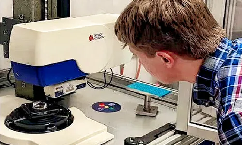
- Non-contact optical profilometers and white-light interferometers for sub-micron surface topography mapping.
- Laser interferometric evaluation against design CAD models.
- Automated coordinate measuring machines (CMM) utilizing ultra-low force ruby styli or non-contact confocal sensors.

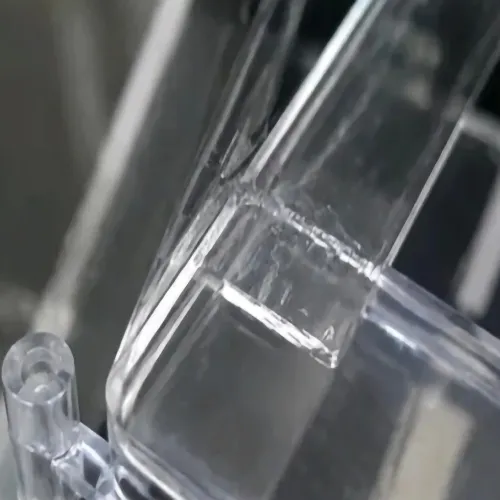
Weld Line and Knit Line Defect on Transparent Injection Molded Parts
5. Defect 4: Optical Haze (Cloudiness)

Optical Haze — Internal Cloudiness
High
Optical haze manifests as a cloudy, milky, or matte appearance within the bulk polymer or across the lens surface. It does not present as localized markings, but rather as an overall loss of optical clarity that is especially noticeable under intense, directed illumination.
Optical Performance Impact: Haze represents forward light scattering, defined as the percentage of transmitted light that deviates by more than 2.5° from the incident beam axis. In precision imaging lenses, even low haze values (1–2%) significantly degrade contrast by washing out fine spatial frequencies. In illumination and LED lenses, haze causes severe luminous efficacy losses and generates a halo effect around light sources.
Root Cause
- Thermal resin degradation: Excessive barrel temperatures or excessive residence times break down the polymer chains, generating light-scattering micro-molecular fragments.
- Material cross-contamination: Incomplete purging of prior resin runs or cross-contamination from incompatible material grades.
- Localized micro-crystallization: Occurs when molding semi-crystalline polymers under incorrect thermal conditions, allowing micro-crystalline domains to form.
- Mold surface fouling: Cumulative deposits of outgassed additives, volatile monomers, or residual mold release agents on the mirror-polished inserts.
- Ejection micro-scratching: Surface scuffing caused by abrasive part release from unpolished tool surfaces or improper mechanical handling.
Prevention Strategies
- Process Control: Establish tight closed-loop controls over barrel temperature profiles, matching processing temperatures to the resin manufacturer’s exact optical-grade specifications.
- Purge Protocols: Implement a rigorous, multi-stage purging procedure using dedicated optical-grade purging compounds when switching lots.
- Tool Maintenance: Maintain SPI A1 mirror finishes on all optical cavity inserts, utilizing ultrasonic solvent cleaning to remove surface outgassing residue.
- Elimination of Release Agents: Ban the use of topical aerosol mold release sprays on precision optical inserts; utilize internal mold release additives if mandatory.
- Environmental Control: Enclose molding cells in Class 10,000 / ISO Class 6 cleanrooms with automated robot extraction to prevent environmental particulate contamination.
Detection Methodologies
- Dedicated haze meters operating in compliance with (ASTM D1003 / ISO 14782) standards.
- UV-Vis Spectrophotometers to analyze the full transmittance spectrum from visible to near-infrared (NIR) wavelengths.
- AI Colorimetric Machine Vision: Utilizing spectrophotometric line-scan vision arrays to detect subtle, uniform grayscale drops or yellowing indexes that escape human operators.
6. Defect 5: Weld Lines in the Optical Zone

Weld Lines in the Optical Zone
Critical
Weld lines (also called knit lines) form where two melt flow fronts meet and rejoin during cavity fill. In optical lenses, weld lines appear as thin, slightly darker lines on the lens surface or within the bulk material. For mechanical parts, weld lines are primarily a strength concern. For optical lenses, they are a performance concern because the two flow fronts do not fully merge — the molecular orientation at the interface is different from the surrounding material, creating a local discontinuity in optical properties.
Optical Performance Impact: Because the separate melt fronts have experienced cooling prior to contact, their molecular chains do not fully interpenetrate. This incomplete fusion creates a narrow band with localized density and molecular orientation variances, resulting in a refractive index (RI) discontinuity. Light waves striking this interface are refracted and scattered out of their intended path. In structured light or diffractive optical element (DOE) projectors — such as those utilized in humanoid robot depth perception systems — a weld line distorts the projected dot matrix, introducing systematic mathematical errors into the 3D vision algorithms.
Root Cause
- Multiple gate configurations: Using more than one gate on a single lens cavity, forcing multiple melt fronts to collide within the clear aperture.
- Internal flow obstacles: Designing lenses with functional through-holes, alignment slots, or heavy steps that split the single melt front before it recombines.
- Inadequate melt front temperatures: Low melt or mold temperatures reduce the molecular mobility of the polymer chains at the collision interface, preventing adequate interpenetration.
- Low injection velocity: Allows the advancing melt fronts to cool excessively before meeting.
Prevention Strategies
- Tooling Standard: Work with your mold manufacturing partner to enforce a single-gate rule for all symmetric circular lens geometries, eliminating weld line generation entirely.
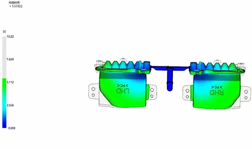
- Advanced Simulation: Utilize multi-variable mold-flow software during design to accurately map melt front advancement and position unavoidable knit lines into non-critical edge flanges.
- Thermal Adjustments: Elevate melt and mold temperatures to maximum allowable processing windows to increase polymer chain diffusion across the weld interface.
- Overflow Tabs: Integrate overflow wells or vents adjacent to the weld zone to draw the initial, cooler melt fronts out of the active optical clear aperture.
Detection Methodologies
- High-intensity transmitted light inspection platforms matched with machine magnification.
- Polarization Imaging: Utilizing polarimetric sensors to isolate the high localized stress concentrations that consistently track along the weld line seam.
- Automated vision inspection using deep learning neural networks to detect faint linear contrast variations.
7. Defect 6: Warpage and Dimensional Instability

Warpage and Dimensional Instability
High
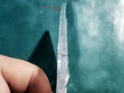
Warpage represents an overall geometric distortion of the lens structure away from its nominal CAD design. It can present as a symmetrical change in surface flatness, an ovality distortion of circular diameters, or an asymmetric twist (saddle deformation).
Optical Performance Impact:Warpage deforms the precision radius of curvature (ROC), altering the lens’s focal length, shifting focal planes, and inducing field curvature. Asymmetric warpage introduces astigmatism, creating two separate focal points along orthogonal meridians. This cannot be compensated for by linear focal adjustments along the optical axis, rendering the assembly non-functional. Furthermore, warped mounting flanges misalign the lens’s optical axis relative to the mechanical housing, disrupting multi-element lens barrel alignment.
Root Cause
- Non-uniform cooling rates: Asymmetric mold tool cooling (where the cavity half operates at a different temperature than the core half) causes uneven localized shrinkage through the part thickness.
- Inadequate cooling time: Ejecting the part before the core has reached its glass transition temperature (Tg), allowing post-molding contraction to warp the unconstrained lens.
- High unbalanced orientation stress: Excessive packing pressures lock high directional stress variations into the part matrix.
- Environmental moisture absorption: In materials like PMMA, uneven post-mold moisture absorption in unregulated storage environments leads to localized dimensional expansion.
Prevention Strategies
- Conformal Cooling Layouts: Use 3D-printed tool inserts featuring conformal cooling lines that trace complex lens curves at a uniform depth, eliminating thermal hot spots.
- Extended Cycle Optimization: Increase the cooling duration based on thermodynamic sensor feedback to ensure full structural solidification prior to mechanical ejection.
- Symmetric Mold Cooling: Balance flow rates and cooling fluid temperatures between the stationary and moving mold halves within plus or minus 1°C.
- Material Selection: Use Cyclic Olefin Polymers (COP) to leverage their near-zero moisture absorption, ensuring long-term post-mold dimensional stability in humid field conditions.
Detection Methodologies
- Laser scanning non-contact profilometers to generate a 3D surface form deviation error map.
- Ultra-precision coordinate measuring machines (CMM) to map profile tolerances (PVor Cpk metrics).
- AI-Assisted Metrology Analytics: Machine learning models that track dimensional trends across successive molding cycles, identifying process drift before parts exceed Upper Specification Limits (USL).
Warpage and Bending Deformation on Transparent Injection Molded Lens
8. Defect 7: Burn Marks and Thermal Degradation

Burn Marks and Thermal Degradation
Medium-High
Burn marks show as distinct dark brown, black, or yellowish discolorations. They can appear as small soot spots at the furthest flow thresholds (gas traps) or as a uniform yellowish tint distributed throughout the bulk optical element.
Optical Performance Impact: Thermal degradation breaks down the polymer chain structure, altering the material’s spectral transmission curve and causing a noticeable yellowing index (YI) shift. In UV-transmitting applications, even minor degradation can block shorter wavelengths entirely. In visible imaging optics, yellowing disrupts white balance and color rendering accuracy. Black carbon specks caused by localized diesel effect ignition introduce total opacity zones, creating dark spots or blind pixels on sensor arrays.
Root Cause
- The Diesel Effect (Air Trapping): High-velocity melt fronts trap air pockets within dead zones or unvented corners of the cavity. The rapid compression of this trapped air generates extreme localized thermodynamic heating, scorching the adjacent polymer.
- Excessive barrel temperatures: Operating the plasticizing unit above the resin’s thermal ceiling.
- Prolonged material residence times: Using an oversized injection barrel relative to small part shot weights, allowing molten resin to break down thermally over extended cycles.
- Melt stagnation zones: Scratches, pits, or poorly engineered check valves within the injection barrel that trap small volumes of resin, causing long-term carbonization.
Prevention Strategies
- Vent Optimization: Run comprehensive mold-flow filling simulations to pinpoint exact gas trap coordinates before cutting steel, and integrate high-permeability micro-vents at those locations.
- Velocity Profiling: Program a deceleration stage into the injection velocity profile right as the melt reaches the end of the fill path, giving trapped gas time to escape through the vents.
- Equipment Matching: Match screw diameter and barrel volume to the specific multi-cavity shot weight, maintaining a target residency window of 2 to 3 shots.
- Thermal Calibration: Implement multi-zone PID controllers along the barrel to prevent localized heater band overshoot.
Detection Methodologies
- Transmission inspection booths utilizing calibrated high-intensity backlighting.
- Spectrophotometric testing to quantify color coordinates and verify the yellowing index.
- AI Machine Vision Colorimeters: High-speed inline color cameras backed by deep-learning models that inspect 100% of ejected parts for minuscule color space deltas , rejecting parts that exhibit early-stage thermal yellowing.
9. 2026: AI-Assisted Inline Inspection and Zero-Defect Manufacturing
The seven defects described above have been industry challenges for decades. In 2026, advances in automated inspection have transformed the economics and practicality of defect detection — enabling a 100% inspection rate at production line speeds while eliminating human operator fatigue and variability.
IDC estimates that by 2026, over 70% of injection molding operations will deploy advanced machine vision systems integrated with AI. For precision optical lens manufacturing, the convergence of high-speed imaging and machine learning enables true Zero-Defect Manufacturing (ZDM) — a quality framework where defects are captured and corrected before non-conforming parts exit the production cell.
What AI Vision Inspection Detects in Optical Lenses
- Silver streaks and splay: Trained on high-contrast backlit image datasets, AI vision systems flag splay patterns with verification accuracy exceeding 99.5% at full production throughput speeds.
- Surface haze: Real-time, quantitative haze distribution mapping replaces manual offline sampling with a haze meter.
- Weld line location: Deep neural networks detect subtle weld line contrast variations invisible to standard visual inspection.
- Burn marks and discoloration: Colorimetry and machine vision algorithms detect early-stage thermal yellowing undetected by human observers.
- Surface contamination and scratches: Automated optical inspection (AOI) provides particle detection and scratch mapping at sub-millimeter scales.
Digital Twin Integration
Advanced 2026 quality control protocols for optical lenses link automated inline inspection results directly to a digital twin — a real-time computational model of the mold tool and molding process variables. When inspection sensors detect a drift toward a specification limit (such as an increase in localized haze from a specific cavity), the digital twin correlates the optical defect data with active process parameters (mold temperature curves, shot weight variations, and resin lot numbers) to identify the specific root cause driving the drift.
This shifts quality control from reactive sorting (detecting defects post-molding) to predictive intervention (identifying process drift before the system molds out-of-specification components). McKinsey research indicates that implementing smart inline quality control cuts defect response times from an industry average of 50 minutes to under 5 minutes.
Inline AI Vision
100% part inspection at production cycle speeds. Neural networks trained on optical-specific defect libraries. Eliminates statistical sampling errors and human visual fatigue.
Digital Twin QC
Inspection results continuously update the active process model. Detects tool or process drift before parts exceed specification limits. Supports automated closed-loop parameter correction.
Traceability
Every lens is tracked by cavity number, material batch, operator ID, and real-time processing data — supporting audit-ready digital traceability records aligned with automotive and medical quality standards.
ATRMOLD’s Current Approach
At ATRMOLD’s Dongguan facility, our quality control architecture integrates precision metrology (Zeiss CMM, Zygo interferometry, and UV-Vis spectrophotometry) with rigorous statistical process control (SPC) monitoring and targeted inline visual inspection for high-volume optical lens manufacturing. As AI vision systems tailored for optical defect detection mature in 2026, we are actively evaluating their integration into our existing quality infrastructure — specifically for automated haze and silver streak detection on high-volume production lines where a 100% inspection rate provides maximum yield optimization over standard AQL sampling protocols.
10. Quick Reference: All 7 Defects at a Glance
| DEFECT | PRIMARY ROOT CAUSE | OPTICAL PERFORMANCE IMPACT | FIRST PREVENTION STEP |
|---|---|---|---|
| Silver Streaks | Resin moisture above drying spec | Light scattering, transmittance reduction | Verify resin moisture before every lot |
| Birefringence | Gate in optical zone / high packing stress | Wavefront error, polarization disruption | Relocate gate outside optical aperture |
| Sink Marks | Insufficient packing / premature gate freeze | Focal length shift, surface aberration | Increase packing pressure + DFM wall review |
| Optical Haze | Resin degradation or contamination | Contrast reduction, luminous efficacy loss | Control barrel temperature + purge protocol |
| Weld Lines | Multiple gates / flow obstacles | Local refractive index variation, scattering | Single gate + mold-flow simulation |
| Warpage | Non-uniform cooling / high residual stress | Focal length error, astigmatism | Conformal cooling + extended cycle time |
| Burn Marks | Air trap / barrel overheating | Transmittance reduction, yellowing | Add mold venting at predicted air trap locations |
Quick Reference: All 7 Defects at a Glance
The Common Thread Six of the seven defects detailed in this guide are preventable through three upstream engineering controls: proper resin drying and dehumidification, comprehensive optical DFM (specifically gate design and mold-flow simulation), and tightly controlled process parameters backed by SPC monitoring. The defects that reach final inspection are almost entirely traceable to an upstream process control step that was either omitted or incorrectly configured. Detection — whether executed by human operators, AI vision systems, or metrology equipment — remains the final line of defense, not the primary quality driver.
When optical lens production runs face recurring defects that typical press adjustments cannot resolve, the root cause usually resides in the component geometry or mold tool design rather than the molding process. our optical engineering team provides a technical DFM feasibility review to isolate the tooling and design variables driving common defect patterns. If the root cause traces back to cavity wear, gate geometry, or venting, our mold manufacturing team can evaluate and rework the tooling directly. For programs with finalized tooling, our injection molding engineers can analyze your current process parameters, drying logs, and SPC data to pinpoint and resolve production-stage root causes
Experiencing Persistent Optical Lens Defects?
Submit your defective sample metrics, material parameters, and current processing data. Our precision optics engineering team will diagnose the root cause and provide actionable recommendations for design, tooling, or process improvements within 48 hours.
Related Articles & Pages