

What actually determines connector lens quality — material selection, dimensional control, and the molding process discipline required to hold tolerances standard plastic optics weren’t designed for.
This guide covers what actually determines connector lens quality: material selection, dimensional control, and the molding process discipline required to hold tolerances that standard plastic optics simply weren’t designed for.
- What a Fiber Optic Connector Lens Actually Does
- Material Selection for Signal-Transmission Optics
- Dimensional Precision: Where Connector Optics Diverge
- Micro-Scale Molding: Why Size Doesn’t Simplify the Problem
- Process Control: Molding for Transmittance, Not Just Dimension
- Photoelectric Sensor Windows: A Related but Distinct Application
- From Design to Production: What a Connector Optics Program Requires
- Frequently Asked Questions
1. What a Fiber Optic Connector Lens Actually Does
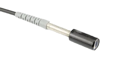
Unlike an imaging lens, a fiber optic connector end-face component isn’t designed to form a picture — its job is to transmit light between a fiber core and a photodetector or emitter with minimal loss, minimal back-reflection, and long-term dimensional stability under repeated mating cycles.
This distinction matters for sourcing decisions. A connector lens or window doesn’t need MTF (modulation transfer function) performance or aberration correction the way a camera lens does — but it demands tighter concentricity, flatness, and surface finish control than most consumer optics ever require, because the fiber core it aligns to is often smaller than a human hair.
Three performance metrics define whether a molded connector component is production-ready:
INSERTION LOSS
Typically < 0.3–0.5 dB for precision applications
RETURN LOSS
Back-reflection control for signal integrity
REPEATABILTY
Hundreds to thousands of mating cycles
Insertion loss — how much signal energy is lost as light passes through the component, typically targeted below 0.3–0.5 dB for precision applications.
Return loss (back-reflection) — how much light bounces back toward the source instead of transmitting forward, which can degrade signal integrity in high-speed data links.
Repeatability across mating cycles — connectors are designed to be plugged and unplugged hundreds or thousands of times, and the lens geometry must maintain alignment tolerance throughout that service life.
2. Material Selection for Signal-Transmission Optics
Material choice for connector lenses is driven by a different priority stack than imaging optics: transmittance stability, dimensional consistency under thermal cycling, and compatibility with the wavelength range in use — typically 850nm, 1310nm, or 1550nm for telecom and datacom applications, or specific visible/NIR bands for industrial fiber sensing.
| Property | Standard Optical PC | Optical-Grade PMMA | Cyclic Olefin Copolymer (COC/COP) |
|---|---|---|---|
| Transmittance stability | Good | Excellent | Excellent |
| Dimensional stability under thermal cycling | Moderate | Moderate | High |
| Moisture absorption | Low | Higher | Very low |
| Typical use case | General connector housings | Cost-sensitive, indoor applications | Outdoor / temperature-variable environments |
For connector components exposed to temperature swings — outdoor telecom cabinets, industrial sensor housings, automotive fiber-optic data links — COC/COP grades are increasingly preferred over standard PMMA specifically because of their low moisture absorption and dimensional stability, both of which directly affect long-term alignment accuracy at the fiber interface.
Material selection interacts directly with molding shrinkage behavior. A resin with inconsistent batch-to-batch shrinkage can shift the effective position of the optical axis by a fraction of a micron — negligible in most plastic parts, but potentially significant at the sub-core-diameter alignment tolerances a fiber connector requires.
3. Dimensional Precision: Where Connector Optics Diverge from Standard Lens Molding
The tolerance requirements for connector end-face components are frequently tighter than for general optical lenses of comparable size, for one structural reason: the component must align to a fixed mechanical reference (the ferrule or fiber core position), not just perform correctly in isolation.
Key tolerance zones typically include:
Concentricity between the optical axis and the mechanical mounting feature — often held within a few microns, since any offset directly reduces coupling efficiency at the fiber interface.
Flatness or curvature accuracy across the optical surface — deviation here changes the effective focal characteristics of the coupling path and increases insertion loss.
Surface finish (Ra) — scattering from an under-polished surface directly reduces transmittance and increases stray light reaching the photodetector.
These requirements are why connector lens tooling is treated as a distinct discipline from general lens tooling within precision optical mold manufacturing — the mold cavity must be built and verified to a coordinate system referenced to the mechanical mounting feature, not just to the optical surface itself, which is a different validation workflow than a standalone imaging lens mold.
4. Micro-Scale Molding: Why Size Doesn’t Simplify the Problem
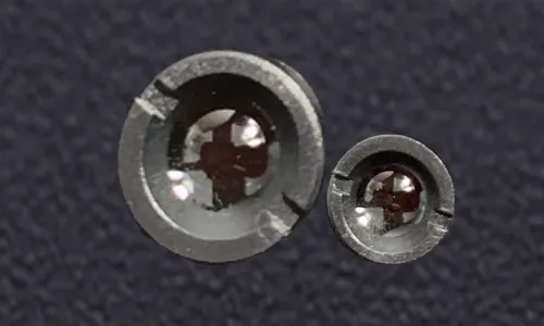
Fiber optic connector components are frequently small — often under 5mm, and in high-density connector arrays, individual lens elements can approach 1mm in diameter. Counterintuitively, smaller parts do not mean simpler tooling.
At this scale:
Gate location becomes a critical optical variable, not just a cosmetic one — a gate placed too close to the optical zone introduces localized stress and flow-line artifacts that measurably affect transmittance.
Ejector pin placement must avoid any contact with the optical surface, which constrains mold design options significantly at small part sizes where surface area is limited.
Shrinkage tolerance stacks up faster in percentage terms — a 0.5% shrinkage variance that’s negligible on a 20mm lens becomes proportionally significant on a 2mm optical feature.
This is the same micro-molding discipline covered in our work on 1mm-diameter optical components for consumer electronics applications — the process controls required to hold tolerance at this scale are consistent whether the end application is a connector, a sensor window, or a miniature imaging component.

5. Process Control: Molding for Transmittance, Not Just Dimension
A connector lens can pass every dimensional inspection and still underperform optically if process parameters aren’t controlled with transmittance in mind specifically.
Melt temperature and injection speed affect molecular orientation in the optical zone. Inconsistent shear during fill can create localized birefringence — invisible on a dimensional CMM report, but measurable as increased insertion loss or polarization-dependent loss (PDL) in fiber-optic testing.
Holding pressure profile determines how completely internal stress relaxes before the part solidifies. For connector components specifically, stress concentration near the gate — the same mechanism responsible for birefringence in other optical applications — can create localized refractive index variation exactly where the fiber core needs the most consistent optical path.
Mold temperature uniformity across small, thin-walled connector geometries is harder to achieve than on larger optical parts, simply because there’s less thermal mass to average out local hot or cold spots — making cooling channel design in the mold itself a determining factor in whether a connector lens meets its transmittance specification consistently, shot after shot.
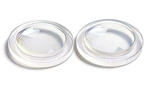
Closely related to connector optics — and often sourced from the same manufacturing capability — are the emitter and receiver windows used in photoelectric sensors: barcode scanners, proximity sensors, and industrial object-detection systems.
These components share the core requirement with connector lenses (transmit light efficiently, don’t image it) but differ in a few important respects:
Emitter windows are typically optimized for a narrow wavelength band matching the LED or laser diode source (commonly red, infrared, or specific laser wavelengths used in barcode scanning).
Receiver windows often require broader spectral transmittance but tighter control over stray-light rejection, since ambient light interference directly affects detection reliability.
Environmental sealing is frequently a bigger design factor than in connector optics — industrial proximity sensors are routinely exposed to dust, oil mist, and washdown cycles that connector components in controlled data-center or telecom environments don’t encounter.
For OEMs designing barcode scanners, presence sensors, or similar photoelectric detection systems, the engineering questions are similar to connector optics: wavelength-matched transmittance, dimensional consistency at small scale, and molding process control tight enough to avoid the birefringence and stress artifacts that degrade optical performance.
7. From Design to Production: What a Connector Optics Program Requires
Manufacturing connector or sensor-window optics that meet insertion-loss and repeatability targets — rather than just passing a dimensional inspection — requires design and tooling expertise integrated from the earliest stage of the program.
A properly structured program typically includes:
DFM Review for Optical Alignment. Drawings are reviewed through optical design engineering analysis specifically for gate placement, mechanical-to-optical alignment tolerance, and ejector interference risk before tooling begins.
Precision Cavity Construction. Mold cavities for connector and sensor optics are built through precision mold manufacturing, referenced to the mechanical mounting geometry rather than the optical surface alone — the distinguishing requirement covered in Section 3.
Cleanroom Molding. Production in a controlled cleanroom environment limits particulate contamination that would otherwise scatter light at the fiber interface, consistent with the process discipline applied across optical lens injection molding production lines generally.
Optical Verification, Not Just Dimensional Inspection. Transmittance and, where applicable, insertion-loss testing on production samples — not solely a CMM dimensional report — since the failure modes covered in this guide (birefringence, stress-induced index variation) are invisible to dimensional inspection alone.
Frequently Asked Questions
What tolerance is typically required for a fiber optic connector lens?
Concentricity between the optical axis and mechanical mounting feature is commonly held within a few microns, with flatness or curvature tolerance on the optical surface set according to the specific coupling requirement. Exact values depend on fiber core size and the insertion-loss budget for the application.
Can the same mold produce both the connector housing and the optical lens element?
It depends on the design. Some connector components integrate the optical window into a single molded part with the housing; others use a separate lens insert assembled into a metal or molded ferrule. Both approaches are supported, and the choice is typically driven by alignment tolerance requirements and assembly volume.
What’s the difference between designing an emitter window and a receiver window for a photoelectric sensor?
Emitter windows are generally optimized for narrow-band transmittance matched to the light source wavelength, while receiver windows often need broader spectral response combined with stray-light control to maintain detection reliability against ambient interference.
Do connector optics need anti-reflective coating?
Many applications benefit from AR coating to reduce back-reflection (return loss), particularly in high-speed data transmission where reflected signal can degrade link performance. Whether coating is required depends on the specific return-loss budget of the application.
What production volumes are typical for custom connector or sensor-window optics?
Prototype and validation runs are typically in the hundreds of pieces for optical and mechanical testing. Production volumes then scale according to the connector or sensor program’s requirements, following the same DFM and tooling validation process regardless of final order size.
Fiber optic connector and photoelectric sensor optics are a different engineering problem from imaging lenses — the goal is efficient, repeatable light transmission at a mechanically referenced interface, not image quality. That distinction changes which tolerances matter, which process variables need the tightest control, and which supplier capabilities actually determine whether a connector program succeeds in production. If your current supplier is applying general-purpose lens tooling practices to a connector or sensor-window program, it’s worth confirming their process is actually built around alignment-referenced tooling rather than optical-surface tooling alone.
Sourcing a Connector or Sensor-Window Optics Program?
Talk to our optical engineering team about DFM review, cleanroom molding, and transmittance verification for your program.
ATRMOLD — Precision Optical Lens Injection Molding & Mold Manufacturing